Preperations
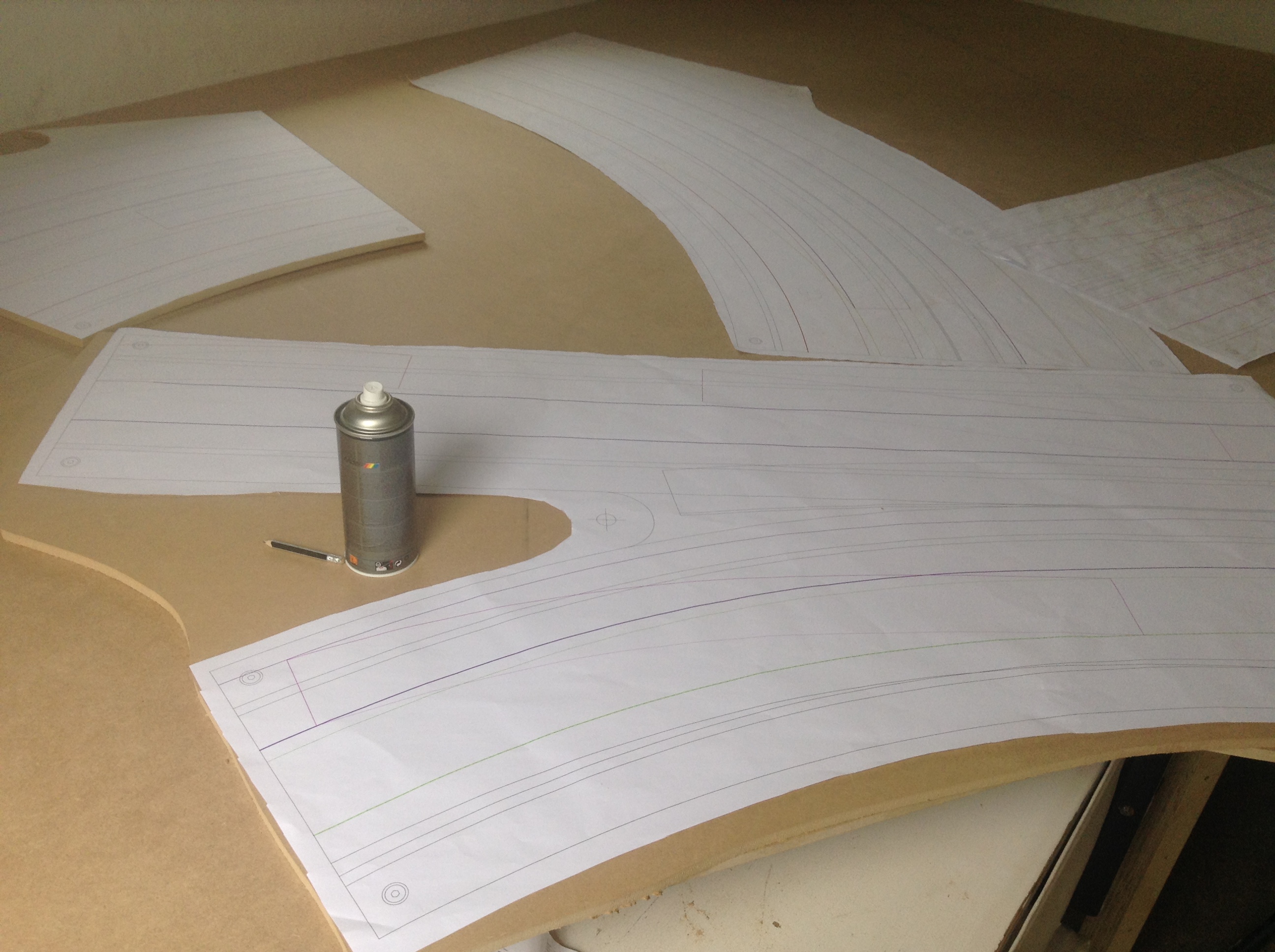
I don’t have a fancy CNC router, which I can feed with a AutoCAD drawing and the output is a “ready to run track”. No I have to print my layout on paper, glue it to the MDF and route it by hand. For this job I use my small 42″ HP printer 🙂 and my Bosch router. I already had one router, but have chosen to buy yet another one, because that will spare a lot of time changing routerbits and adjustments, especially when I work on the back side of my track.
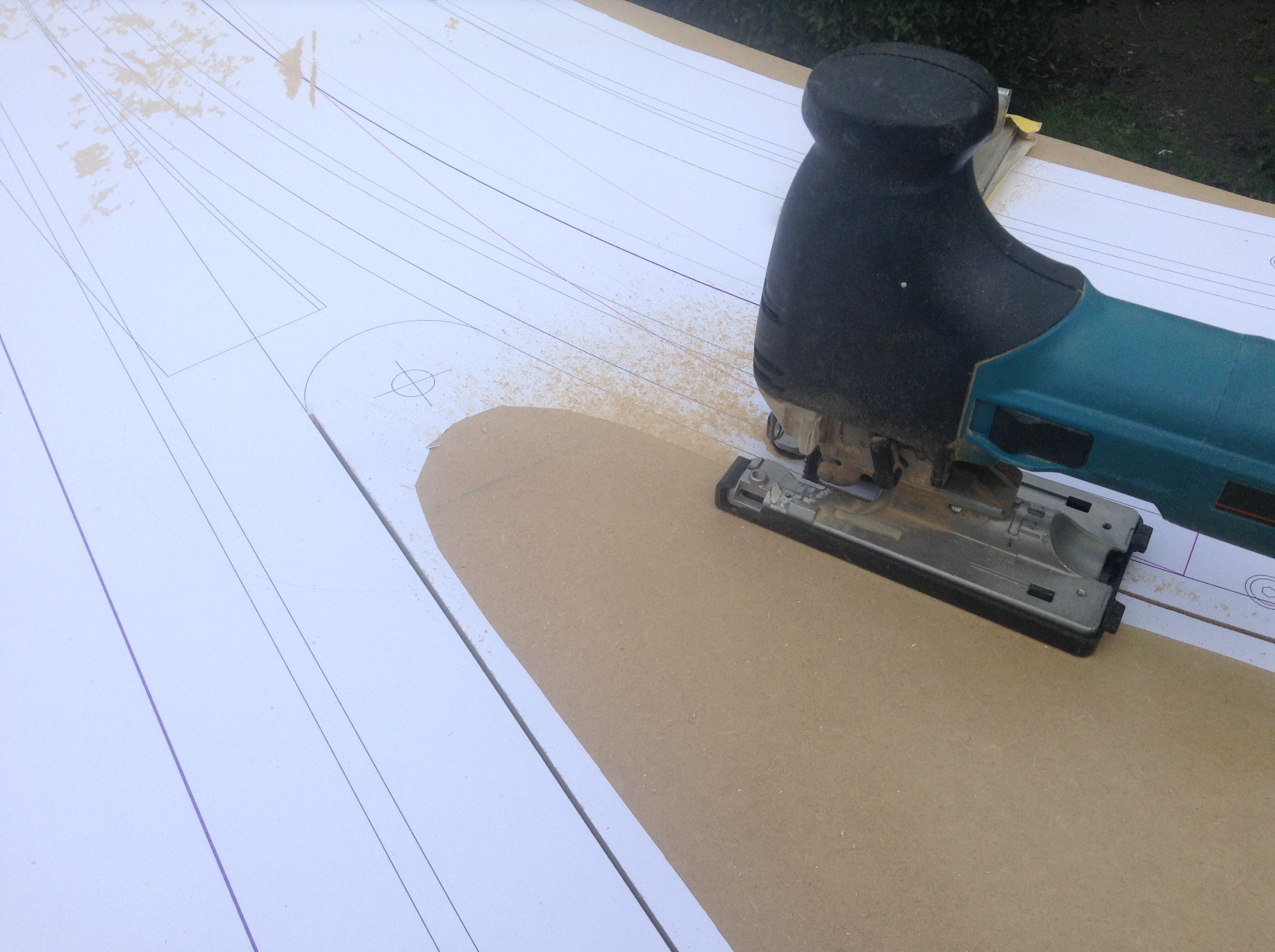
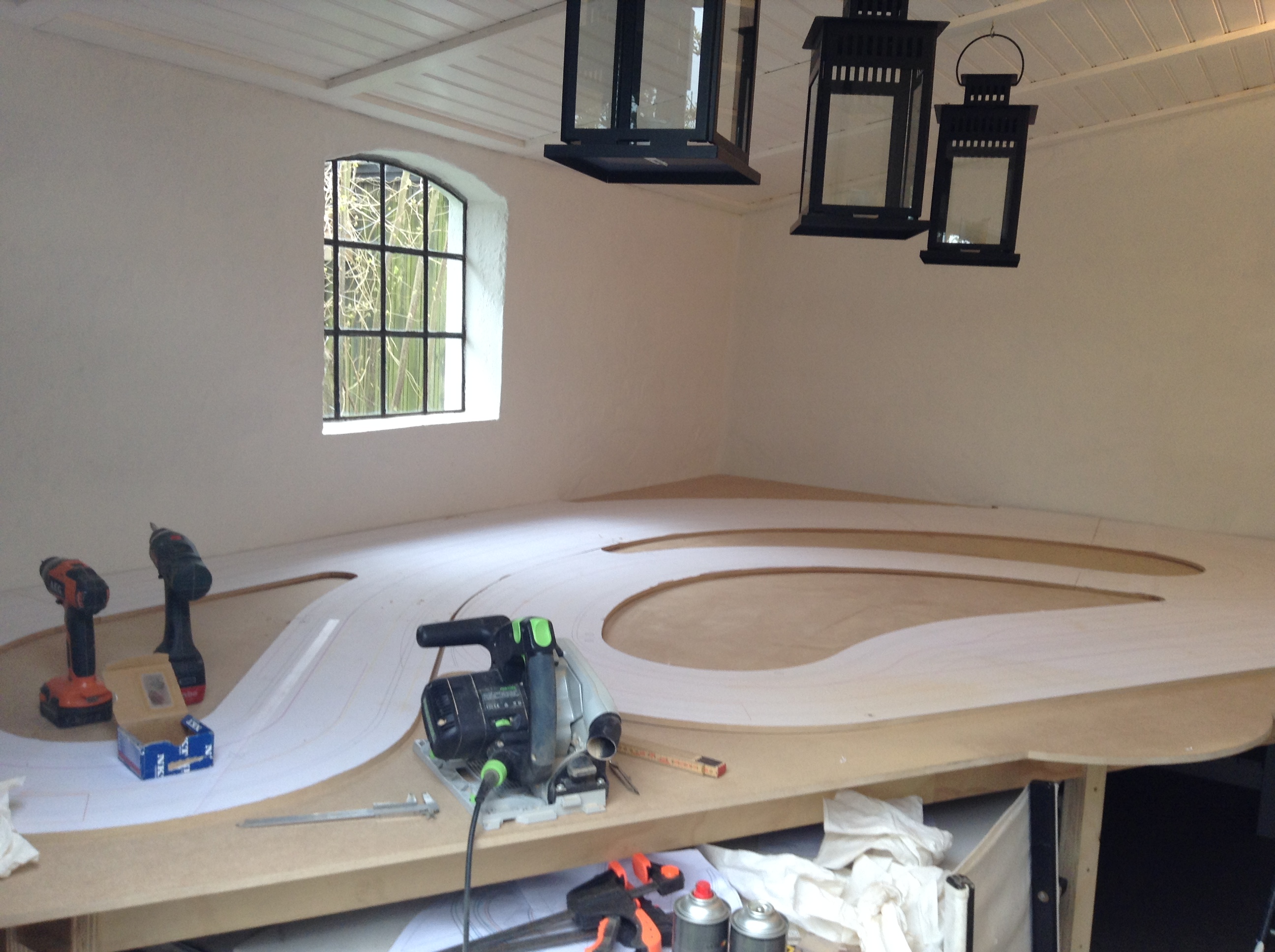
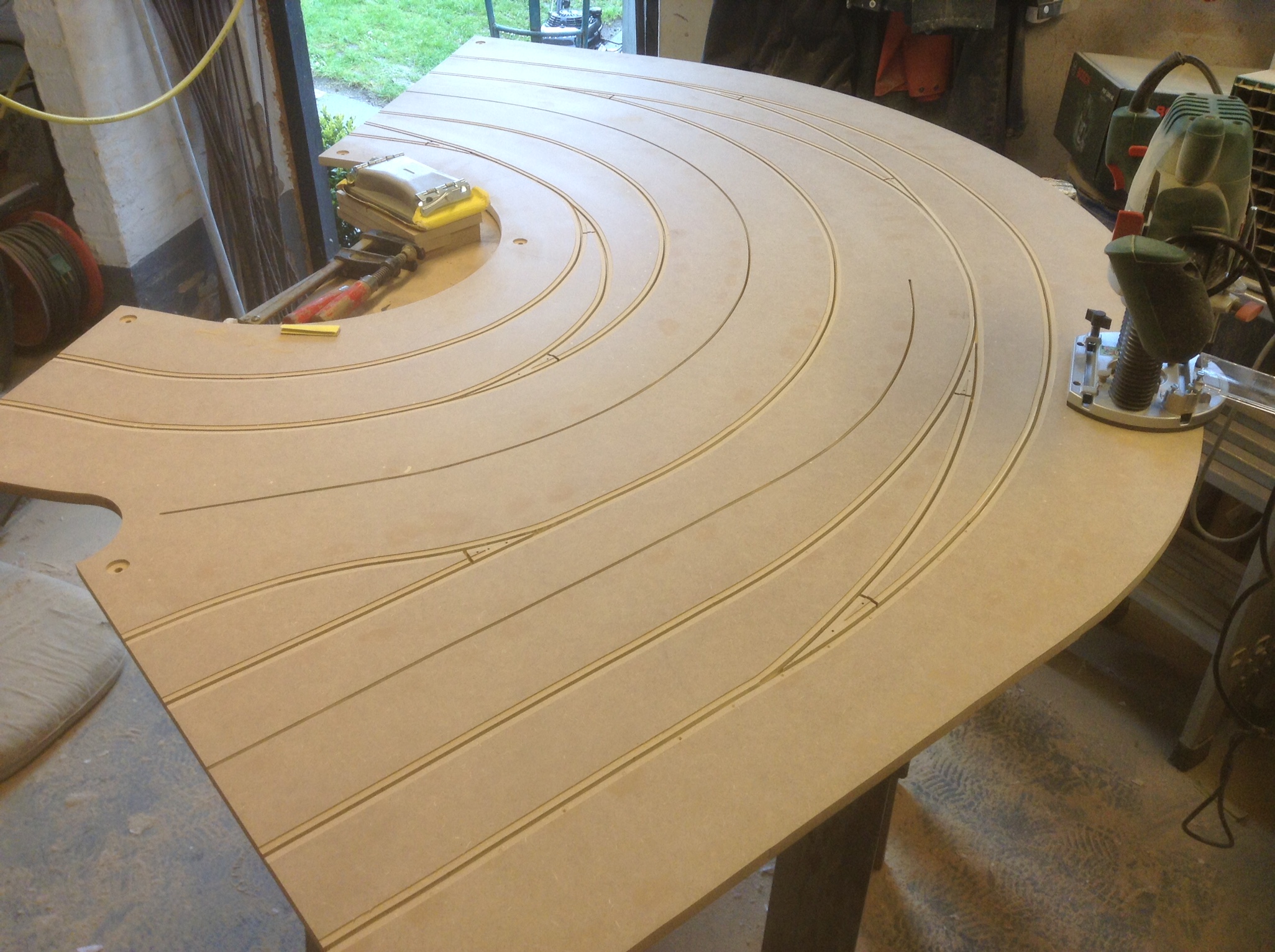
Cutting the sections
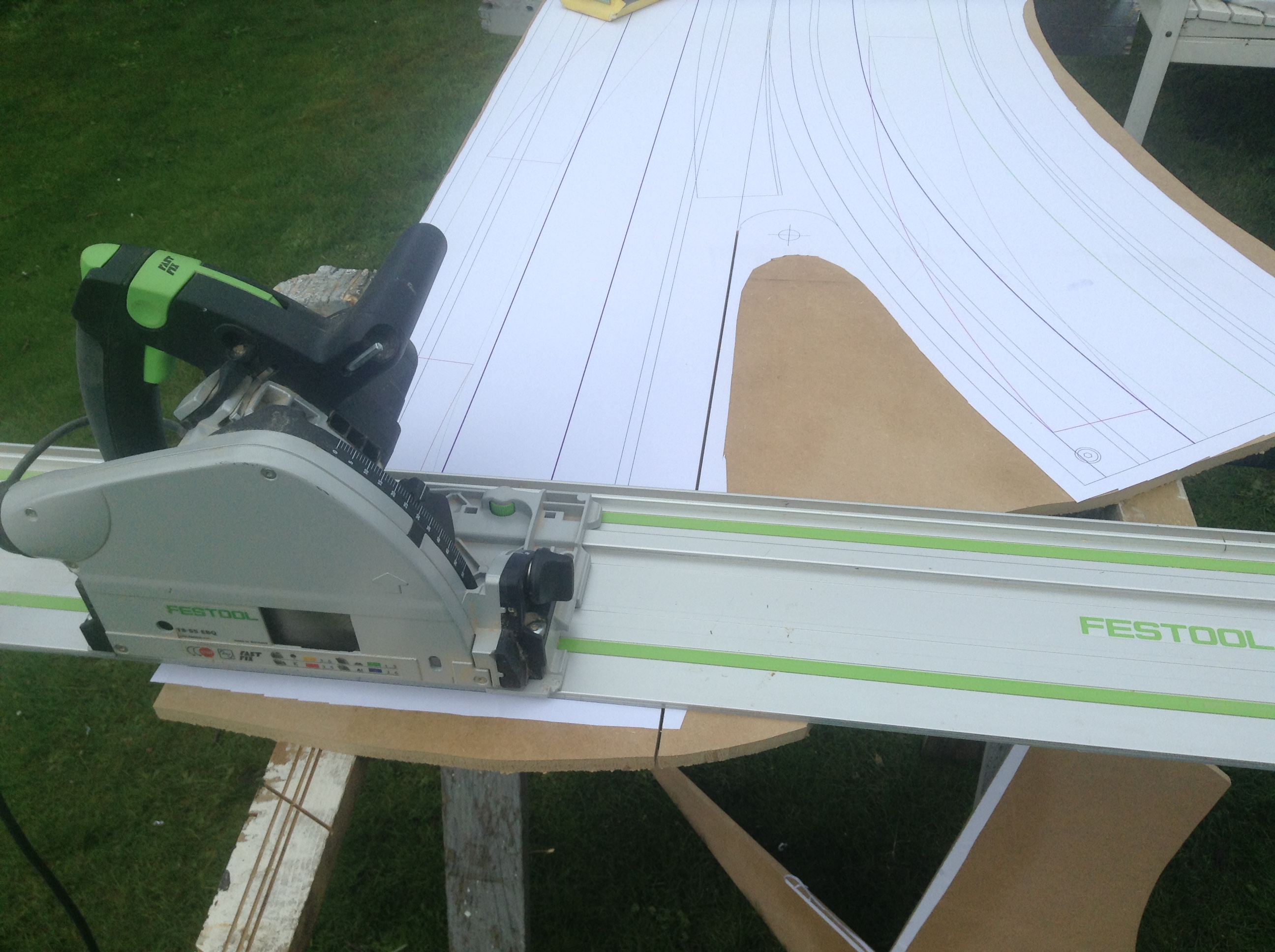
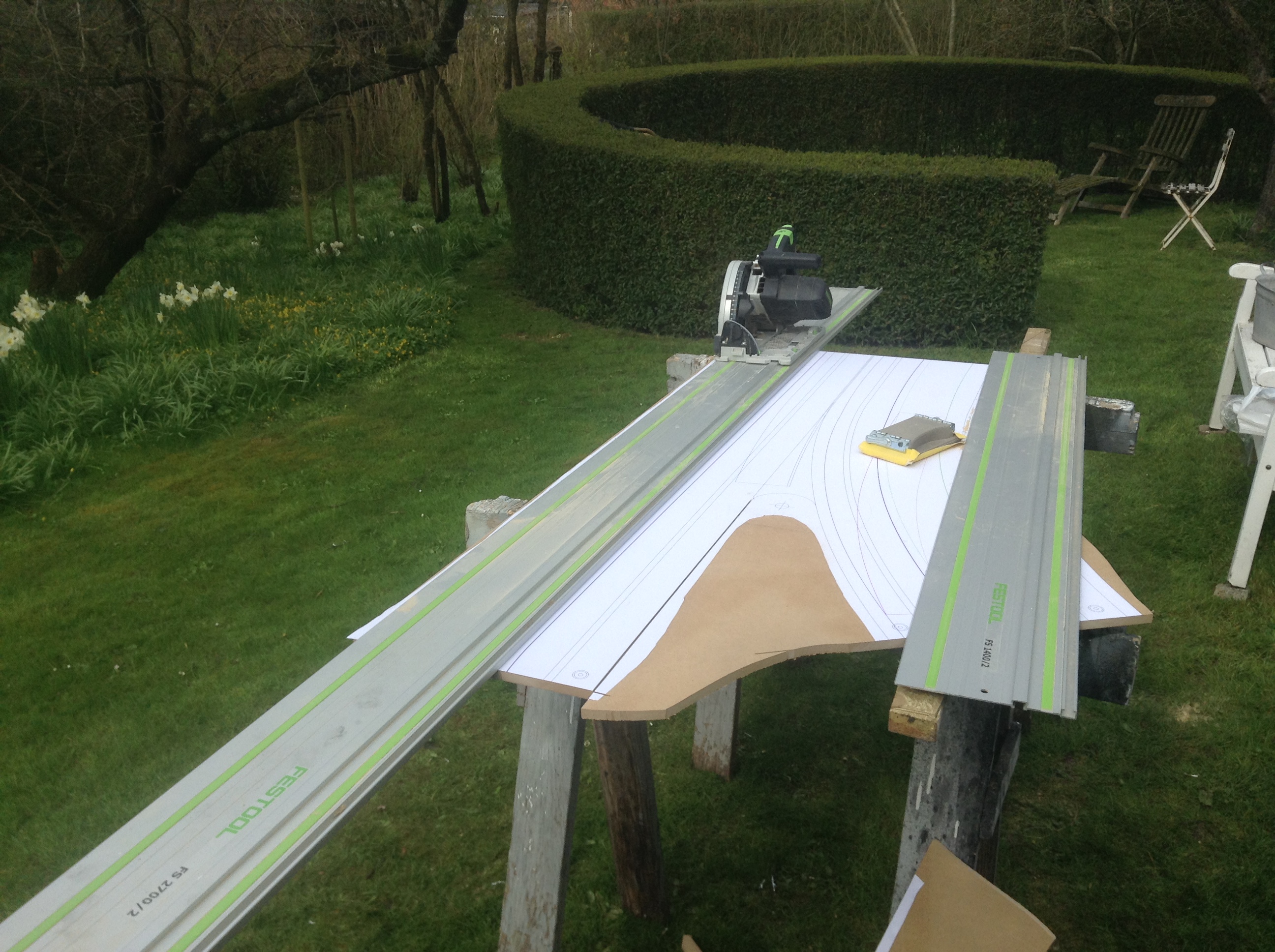
I use 12 mm HDF for the track, it’s pressed together with a water-resistent glue and the increased mass gives a very nice cut. I glue the paper to the HDF with spray glue, cut the straight lines with a Festool plunge saw and the curved with a Makita jigsaw. Afterwards I trim the curves with sandpaper.
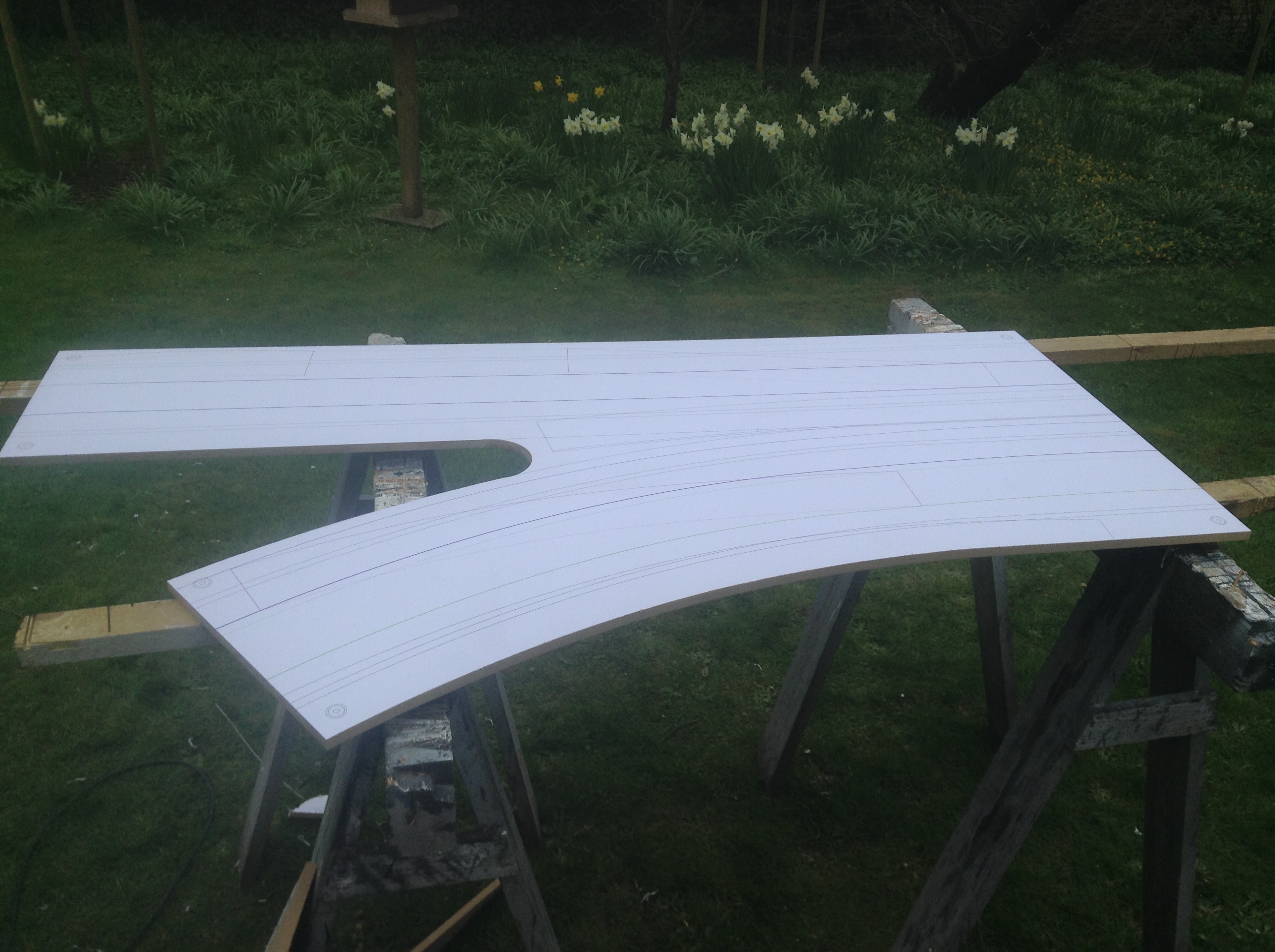
Fix the sections to the frame
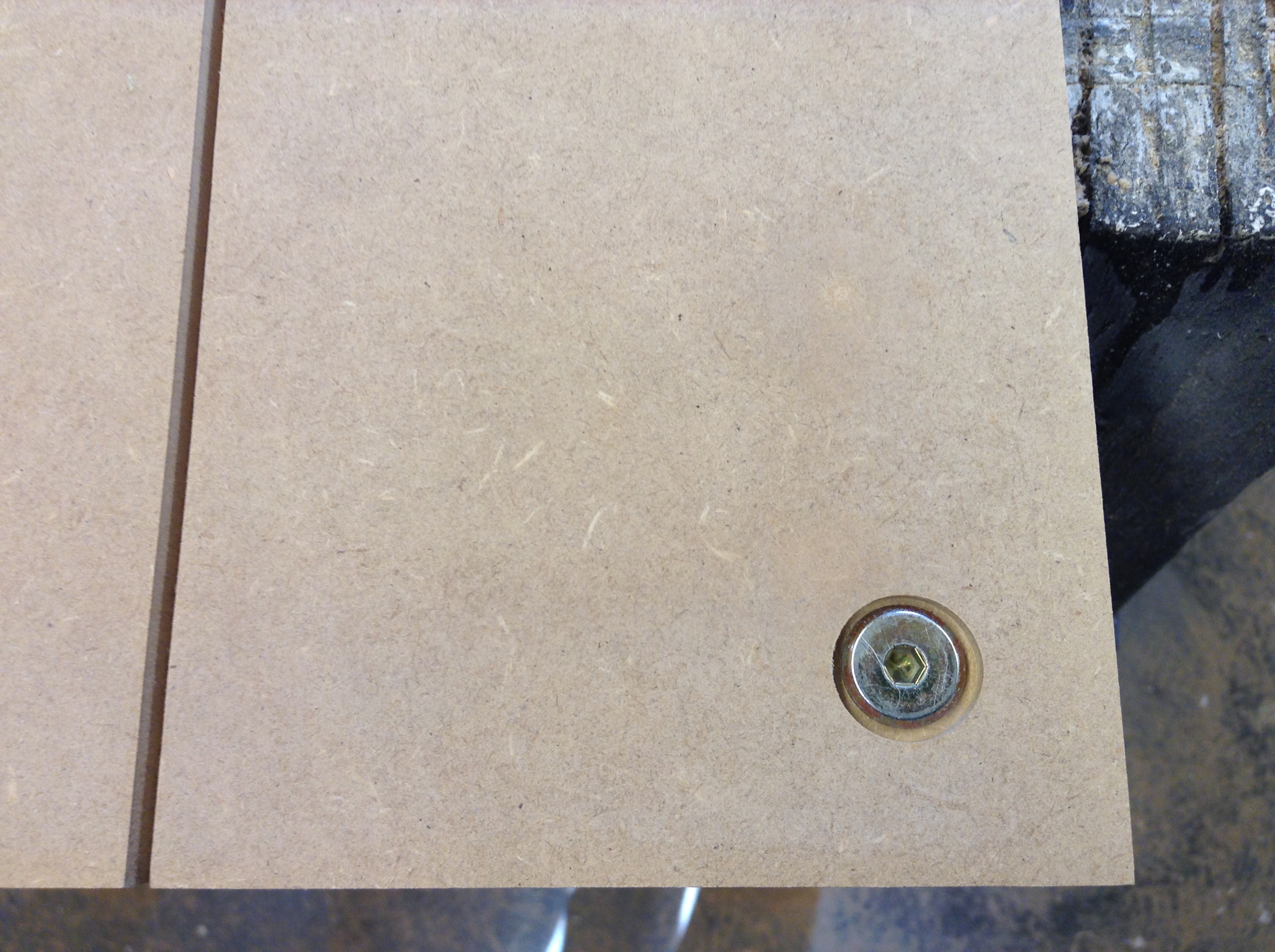
The sections will be fixed to the first layer of MDF (see the Frame submenu) while routing with temporary Tox screws, late they will be replaced with Hex socket screws through the track with Tee nuts mounted underneath the frames MDF. That will keep the sections in right position when racing. I have countersunk the socket screws with my router.
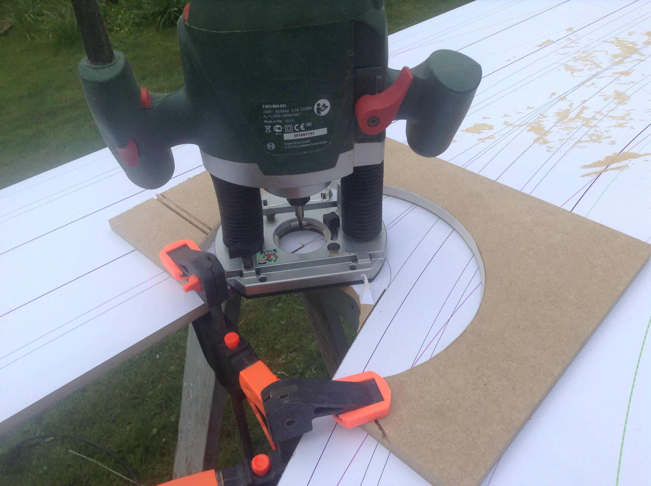
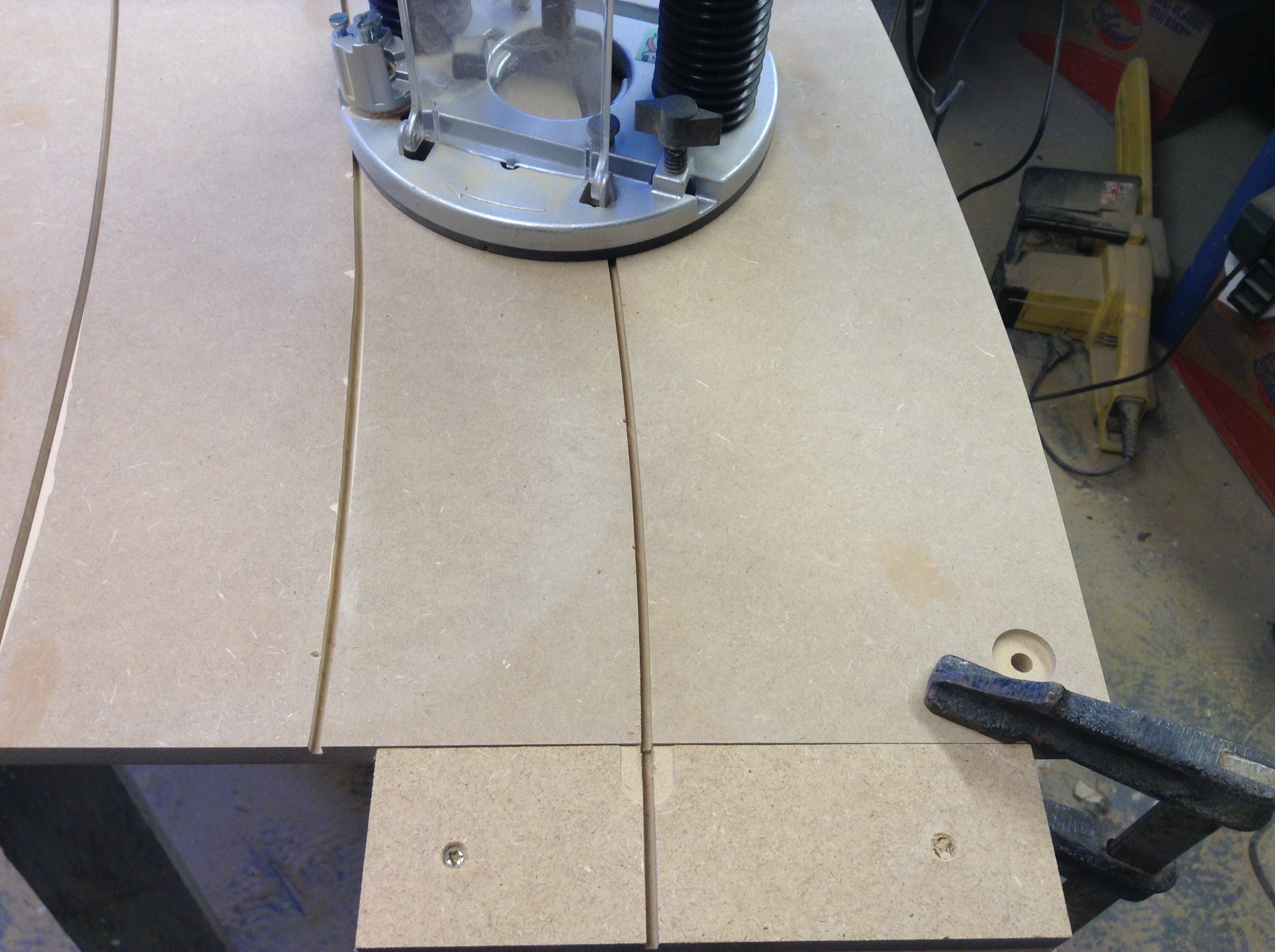
Routing the slots
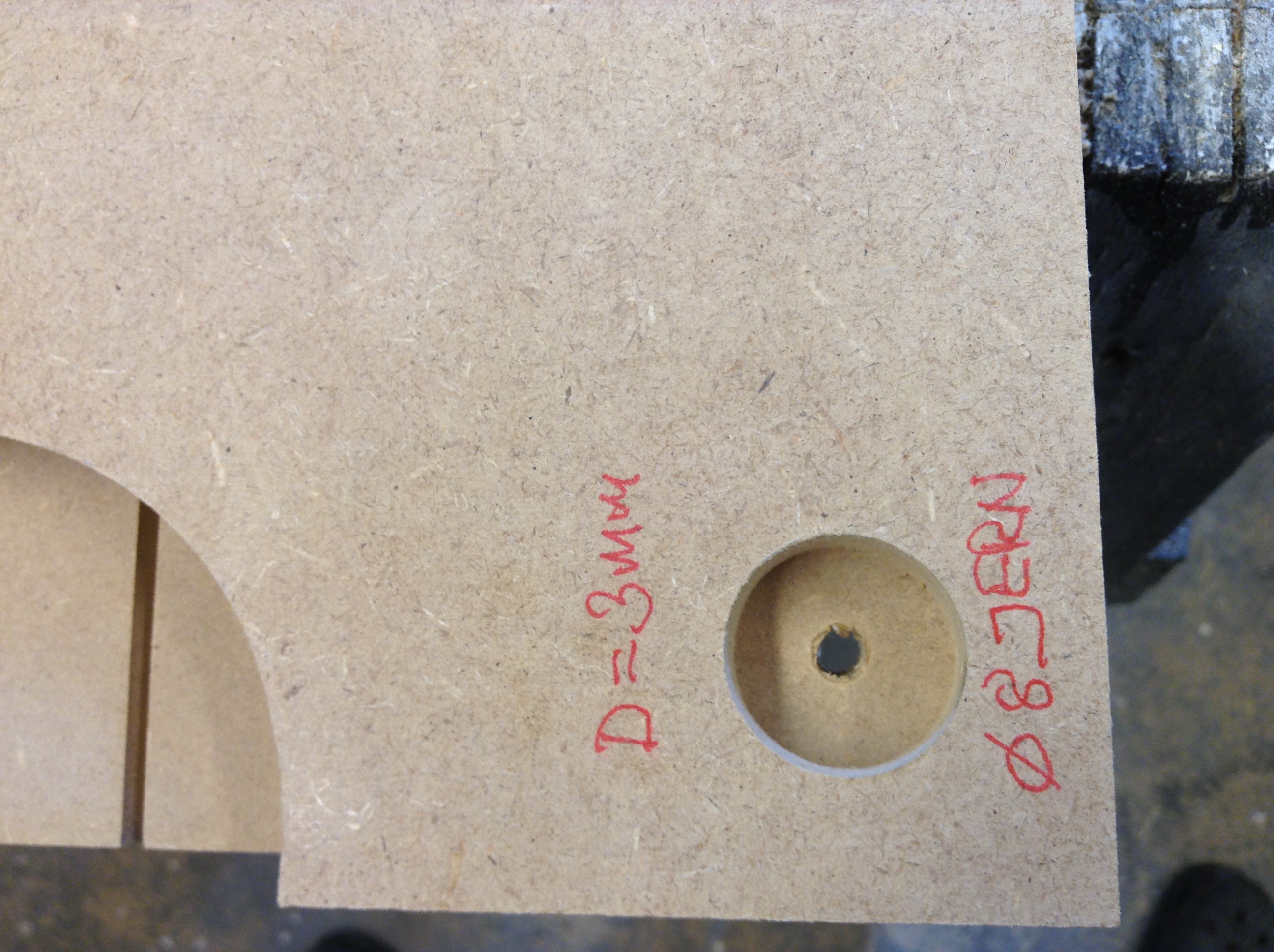
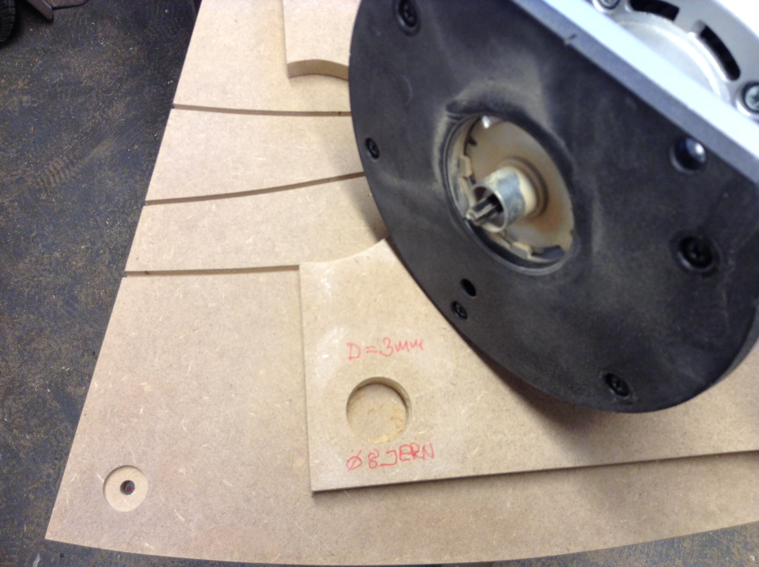
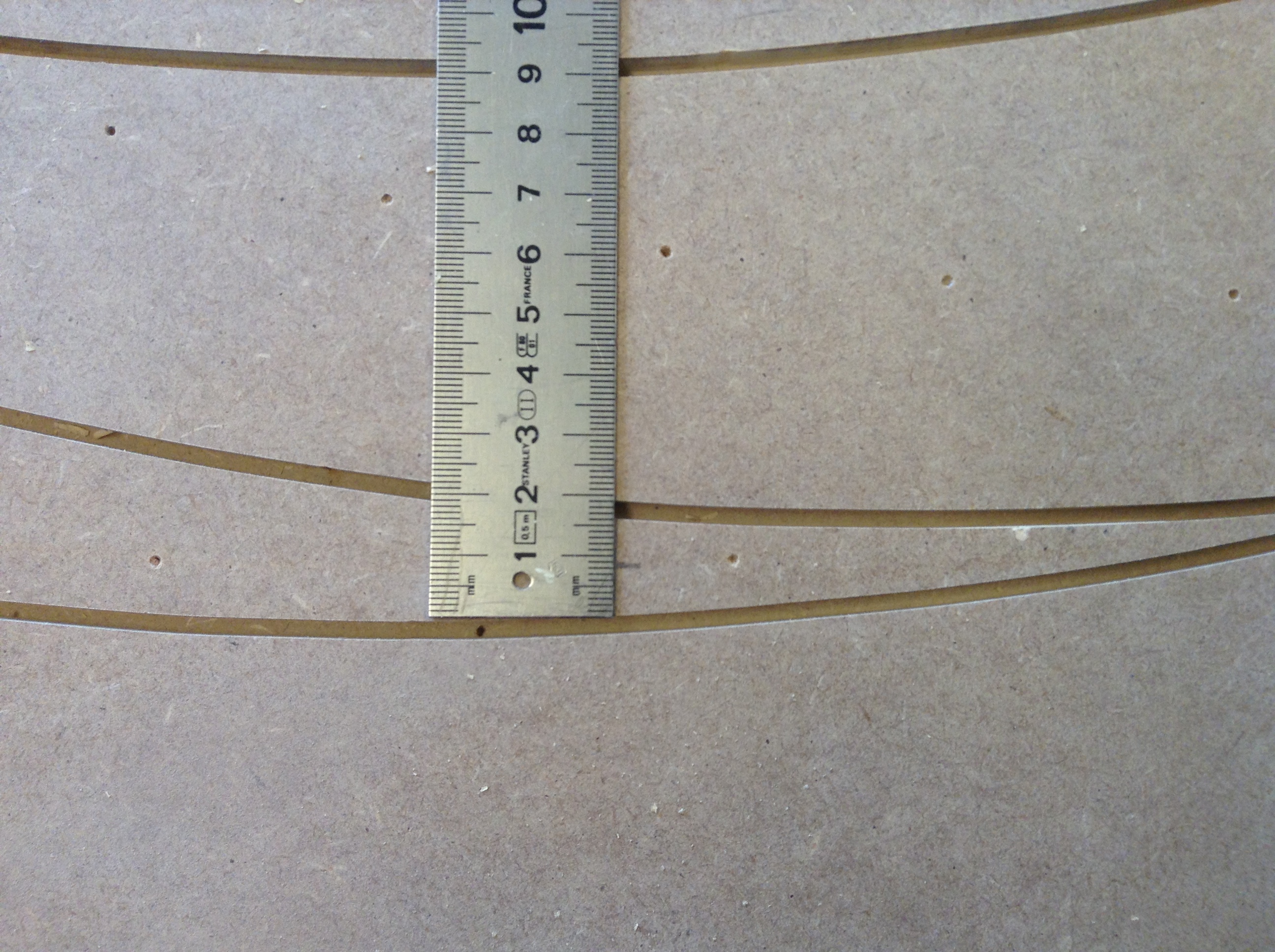
I have bought a 244 cm long flexible plexiglas router base from Luf at oldslotracer – that is an indispensable tool! Luf’s site is also a perfect spot to get lots of inspiration – check it out! The plexiglas base is 6 mm thick with 52 1,9 mm nail holes in the middle.
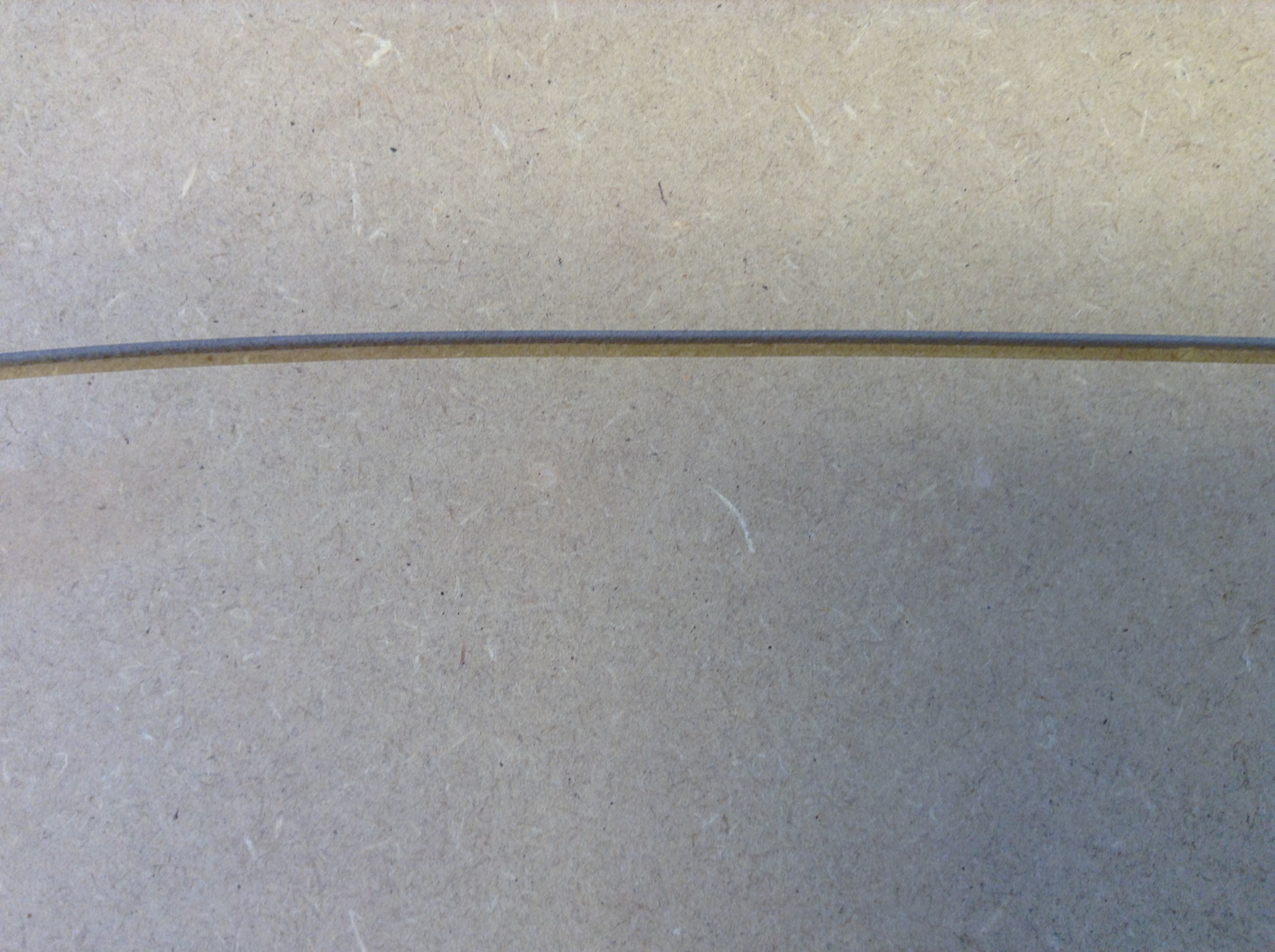
My routers offset is 80 mm, therefore I have to print a baseline with (6/2 + 80) 83 mm parallel offset, as guide for routing the slot. If you don’t draw your track in AutoCAD or similar but by hand on a large piece of paper or perhaps directly on the MDF, the plexiglas base also has that advantage, that it smoothen out your hand drawn lines. The distance between the nail holes on the plexiglas base, is the same all over, which makes it easy to move and fit exactly to its previous location. I have made my slot 6 mm deep and 3 mm wide.
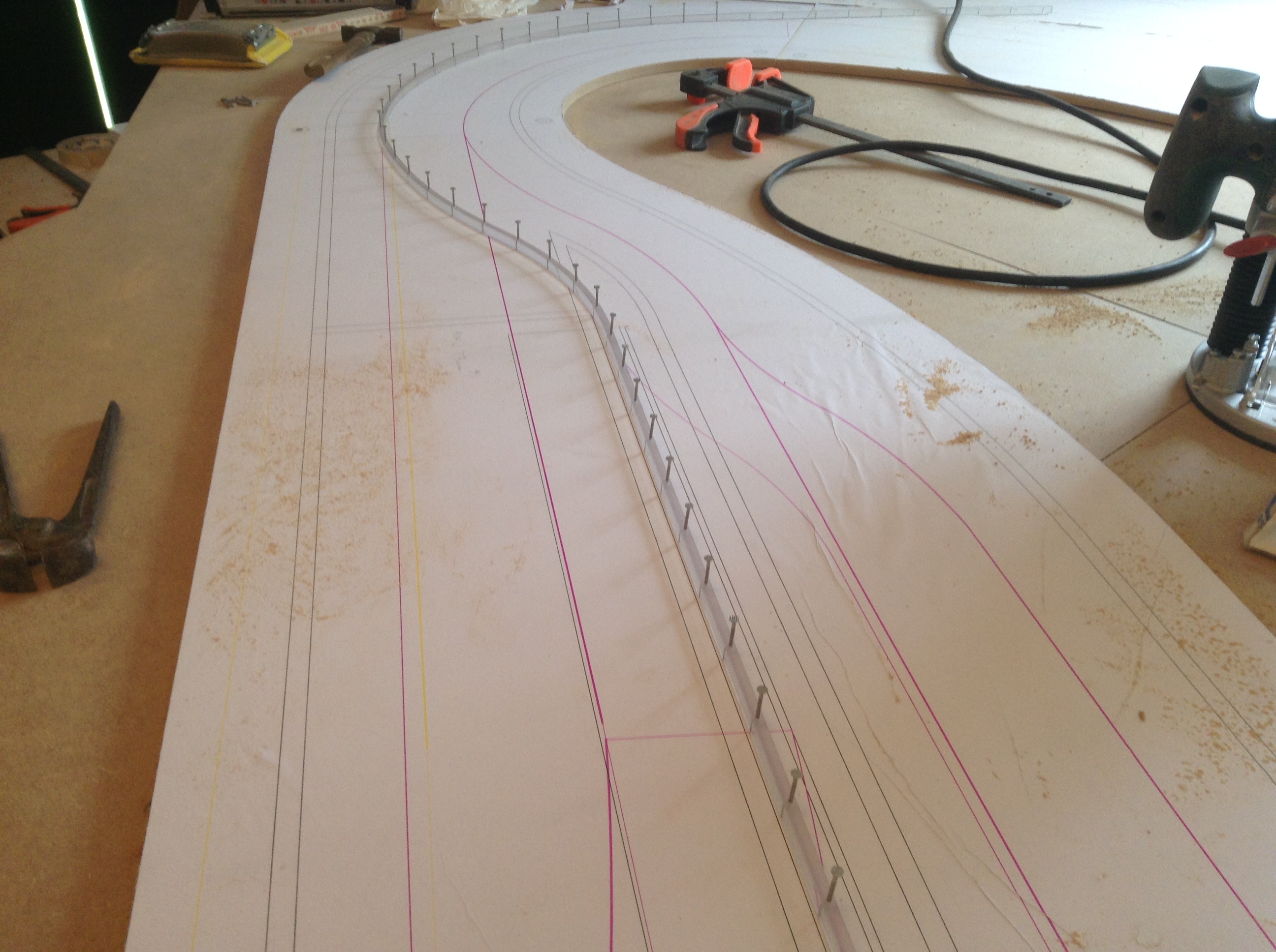
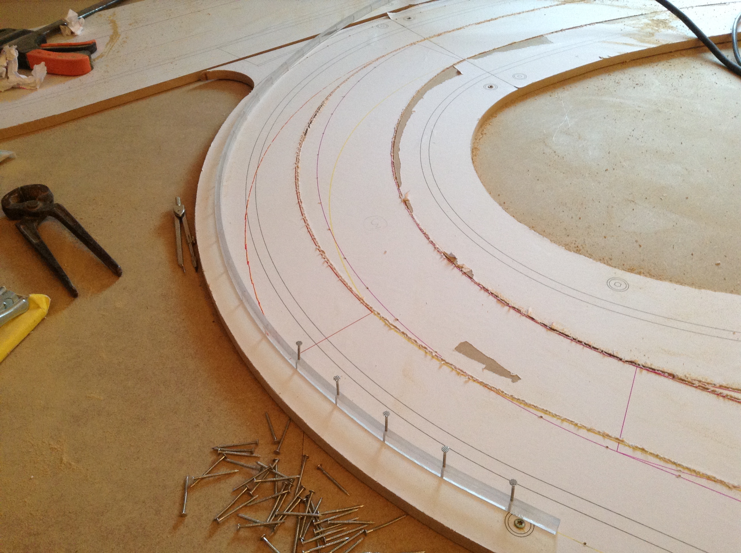
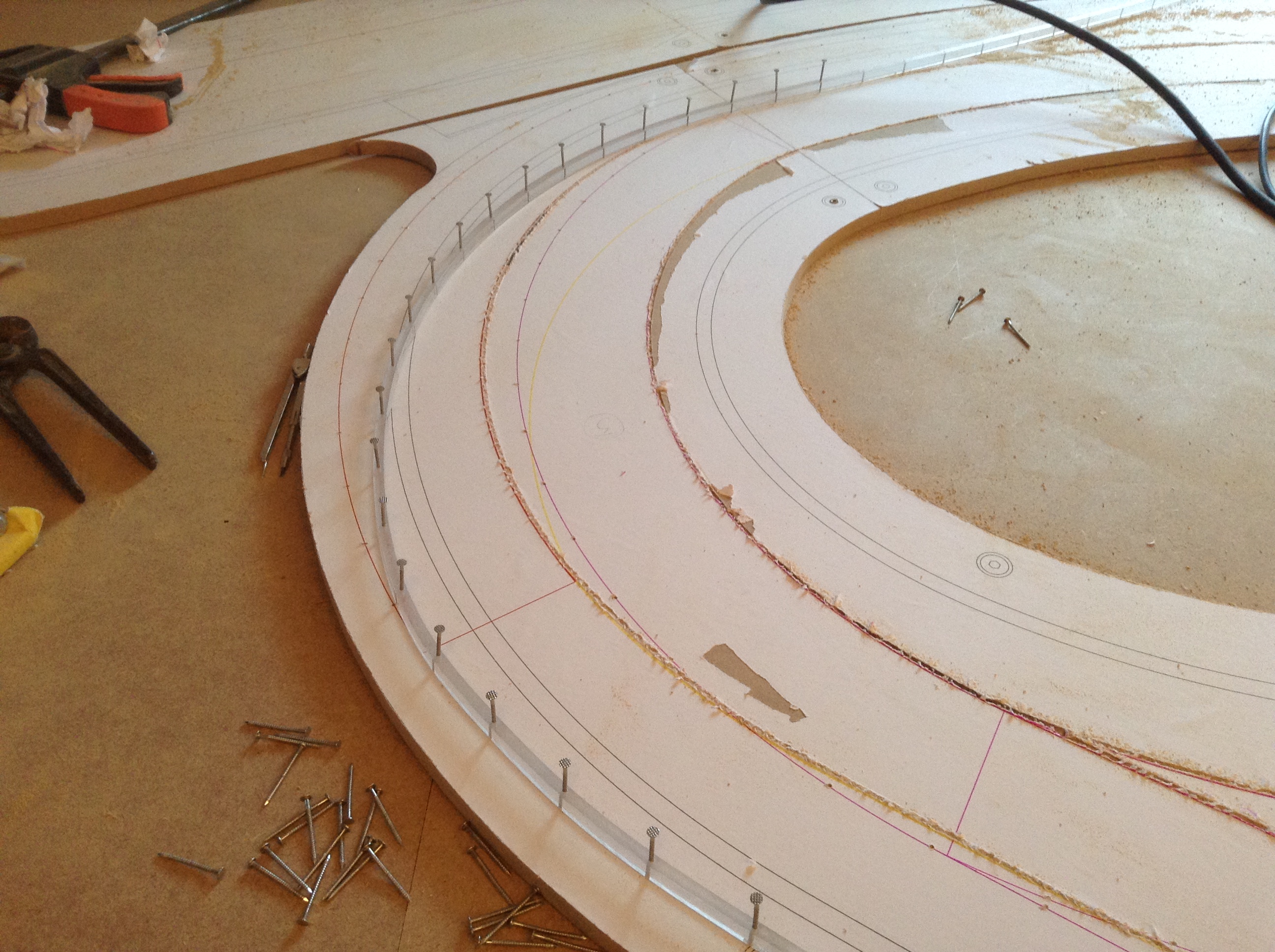
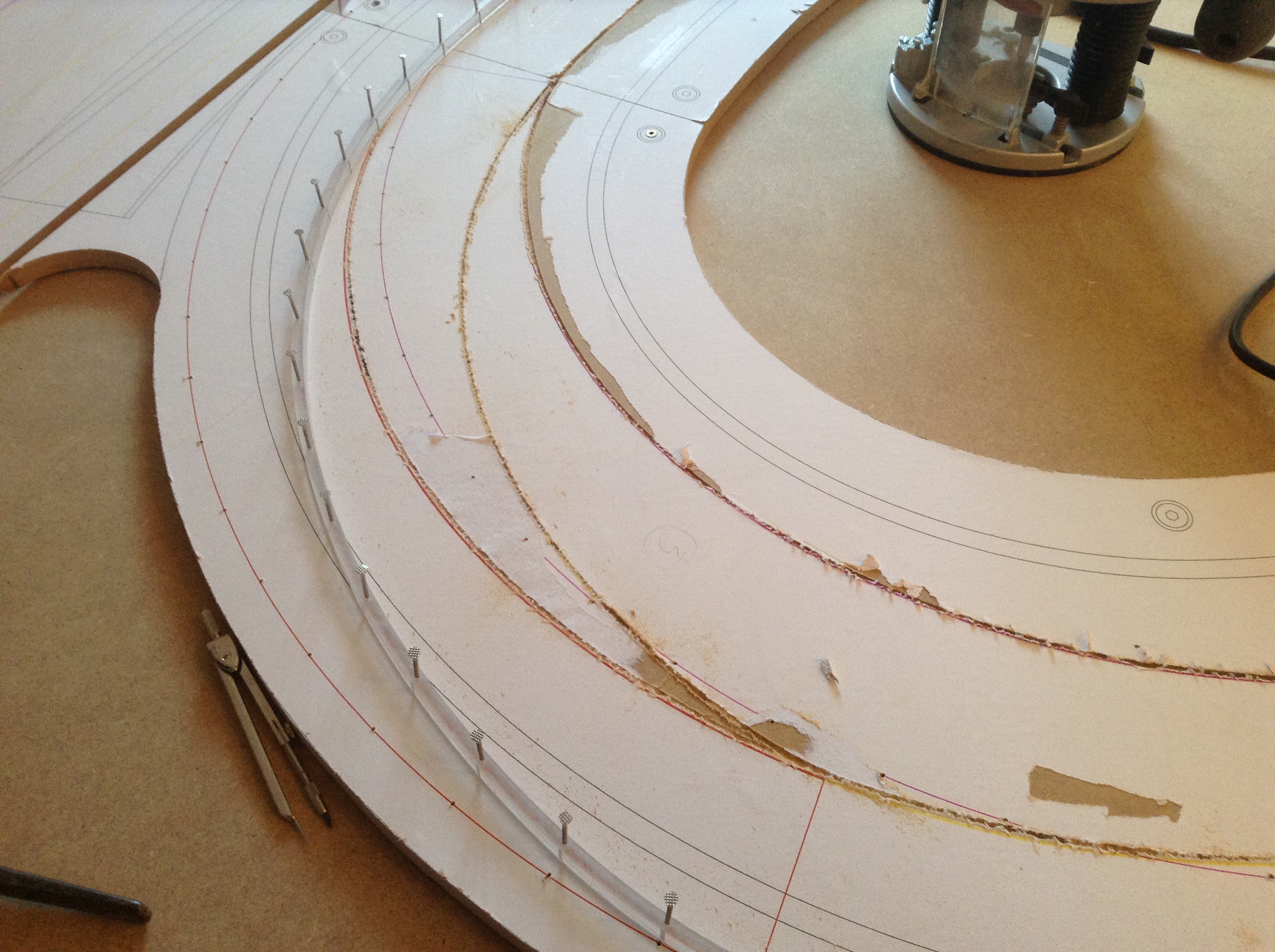
Routing slot for the fence
I want a fence between the sections to prevent chaos when cars are derailed. I make the fence out of 3 mm clear acrylic with a height of 45 mm and mount it in a routed slot.
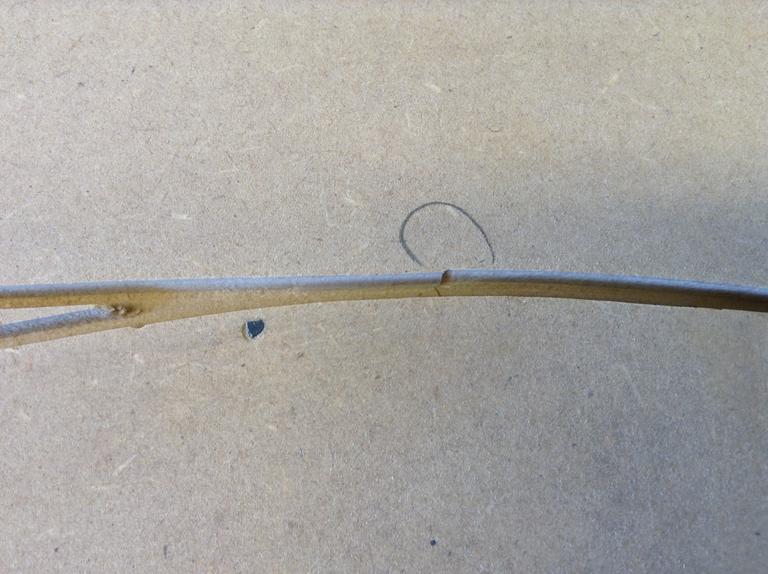
If routing goes wrong
If a slot don’t turn out as planed, just fill it up with a suitable filler (e.g. 2-component Plastic Padding Chemical Wood), let it dry, sand and route a new one.
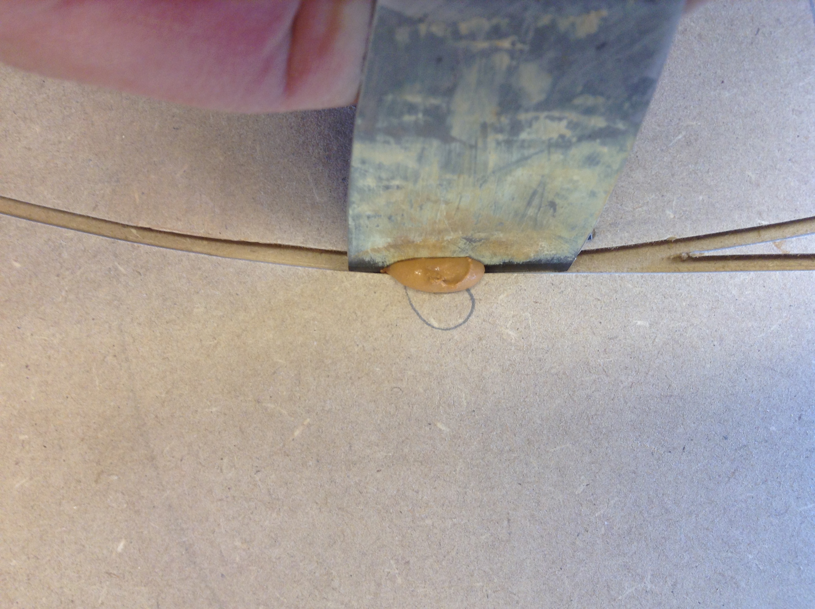
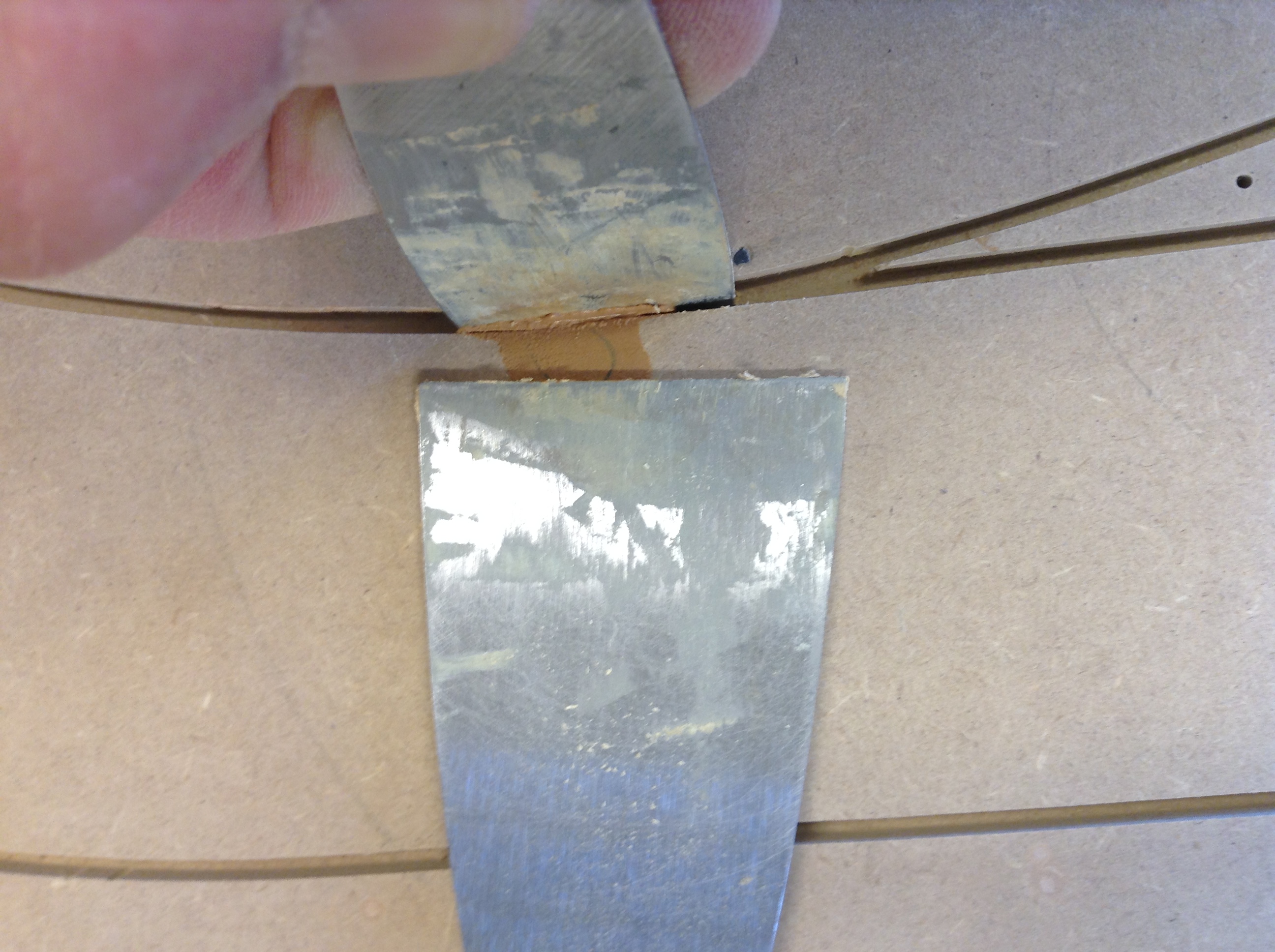
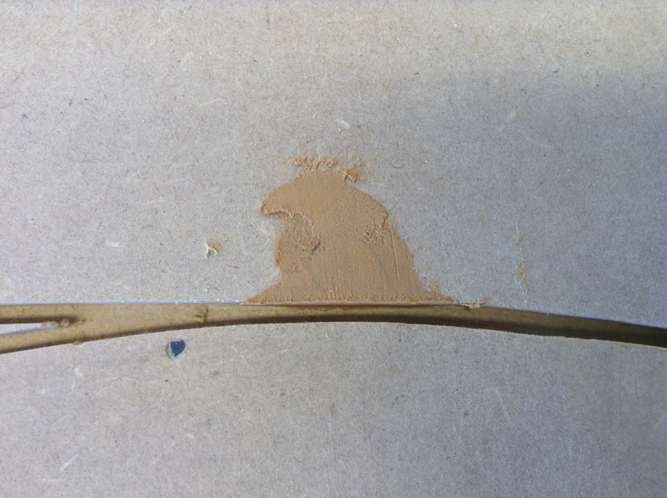
A small bump is easy to remove with sandpaper around a small spatual. On the other hand, if it’s a small punch it can be difficult to plaster inside the slot. However I have found a methode that works for me.
- Put a small amount of filler on a plaster spatual and slide it down into the slot in an angle of 10-15°.
- The filler is now visible on the edge of the slot. Press with an other spatual the filler down between the spatual in the slot and the slot itself.
- Hold the spatual smooth with the surface while raising the other to a 90° position.
- Slide simultaneous the horizontial spatual away from the slot while the vertical one slides to the side.
- It will, with a little practice, result into a satisfied easy to sand repair.
Filling the nail holes
I have not counted the nail holes but I can assure you that there are a lot! Clean the holes with a airgun and fill them with a suitable filler e.g. Polyfilla MDF filler.
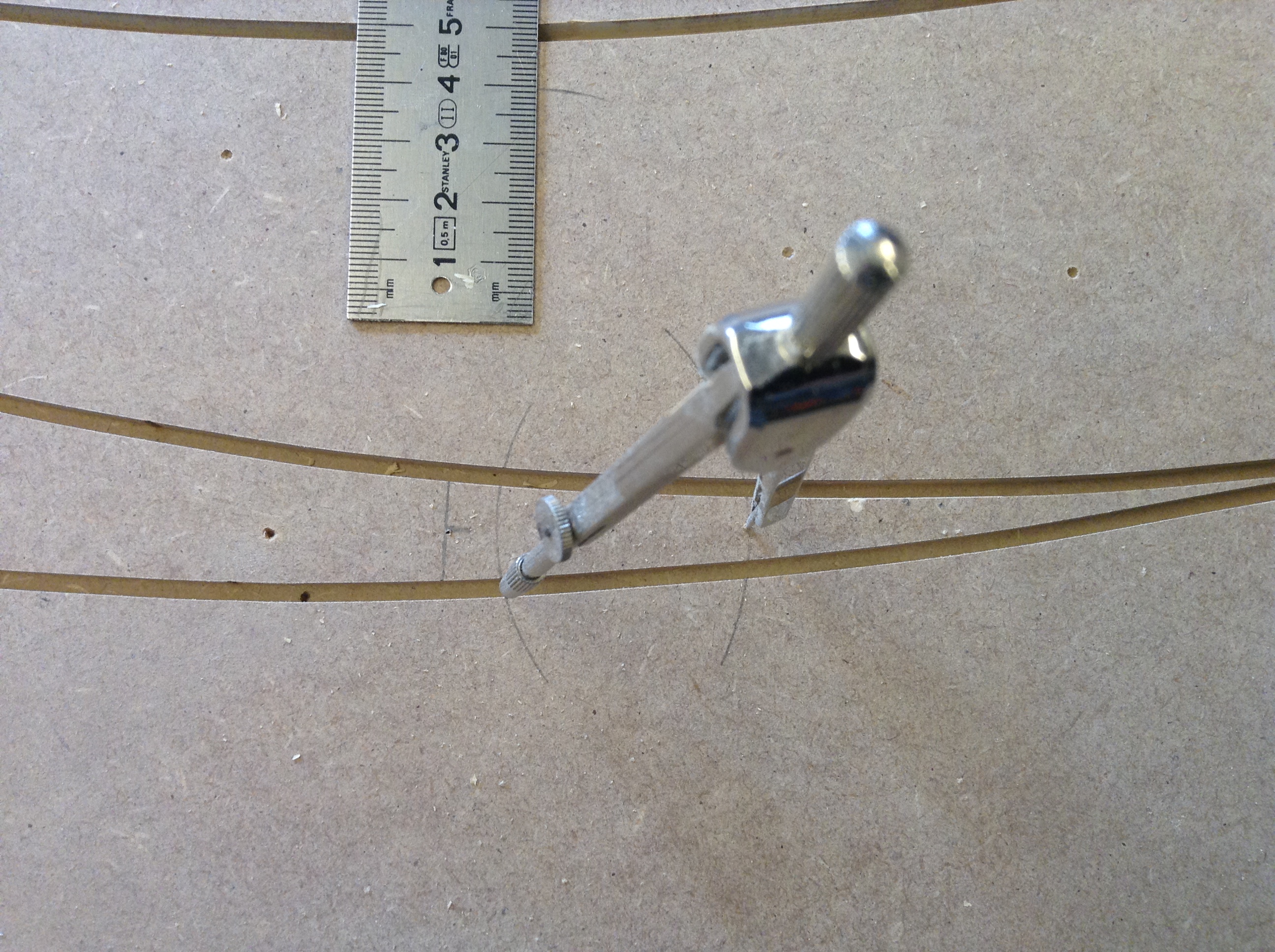
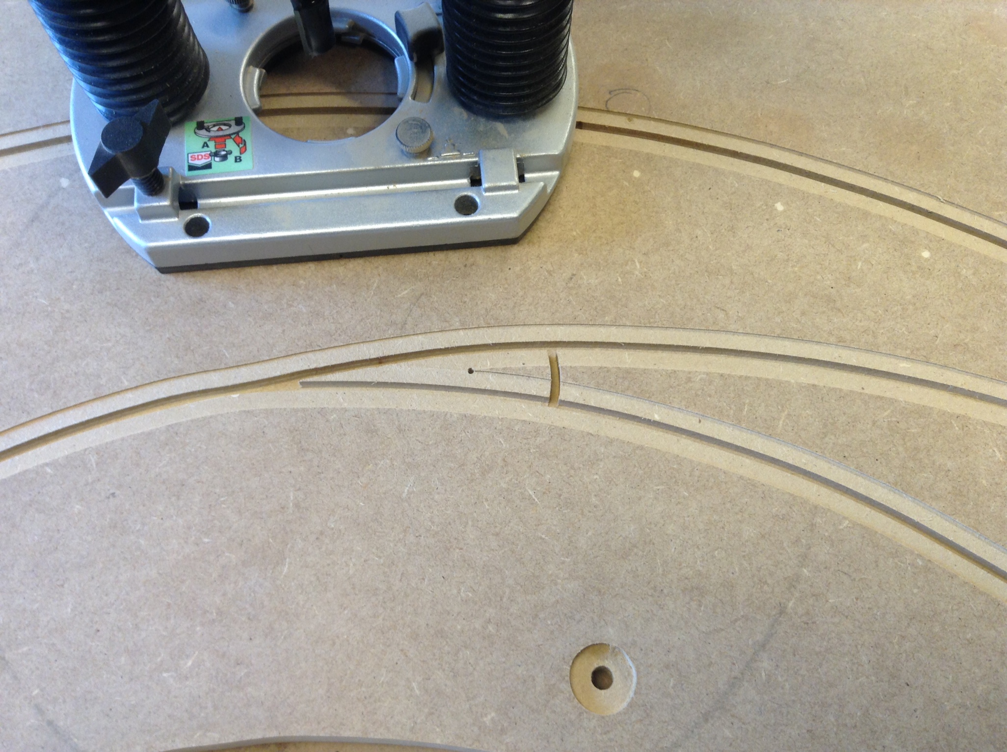
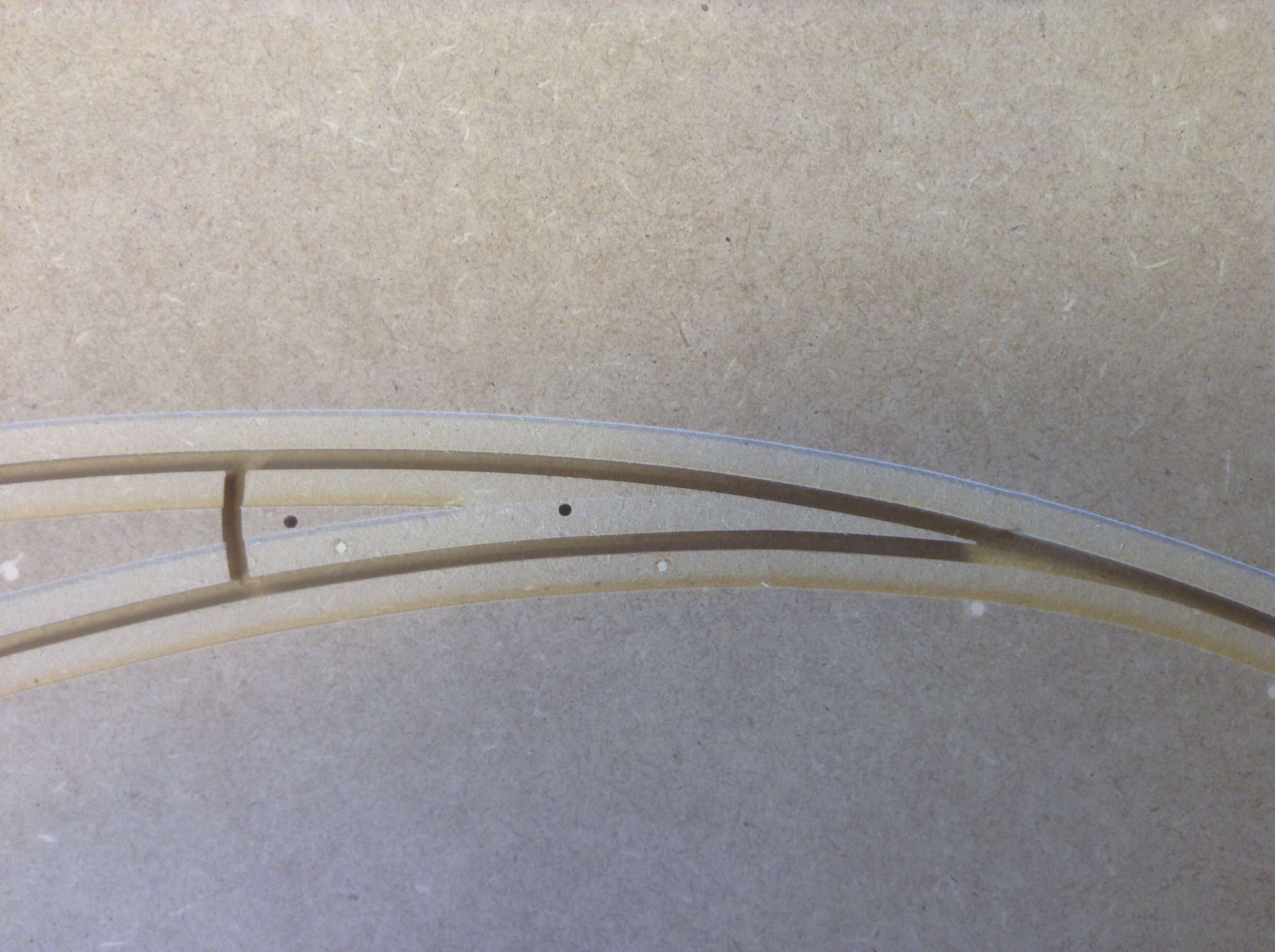
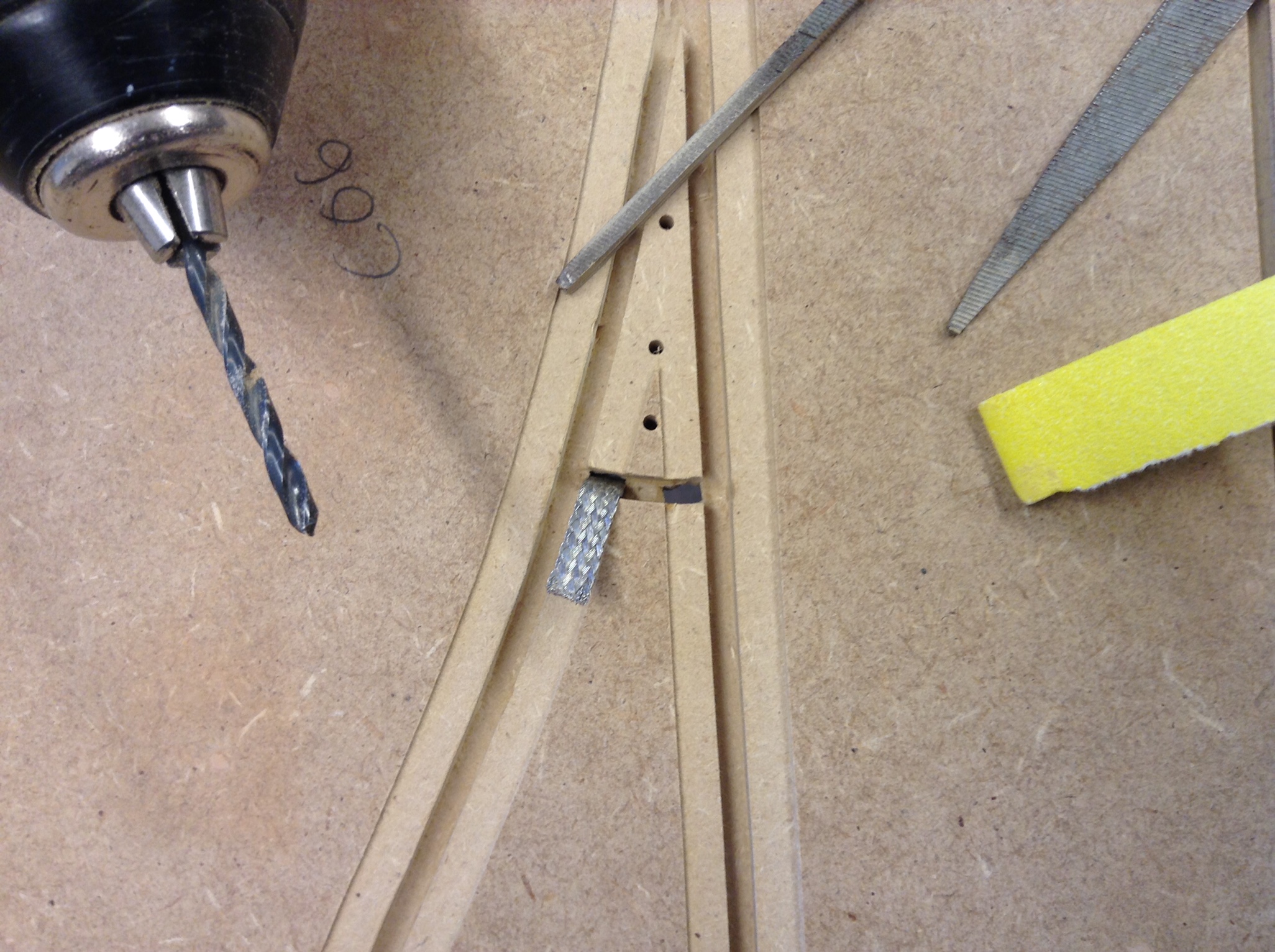
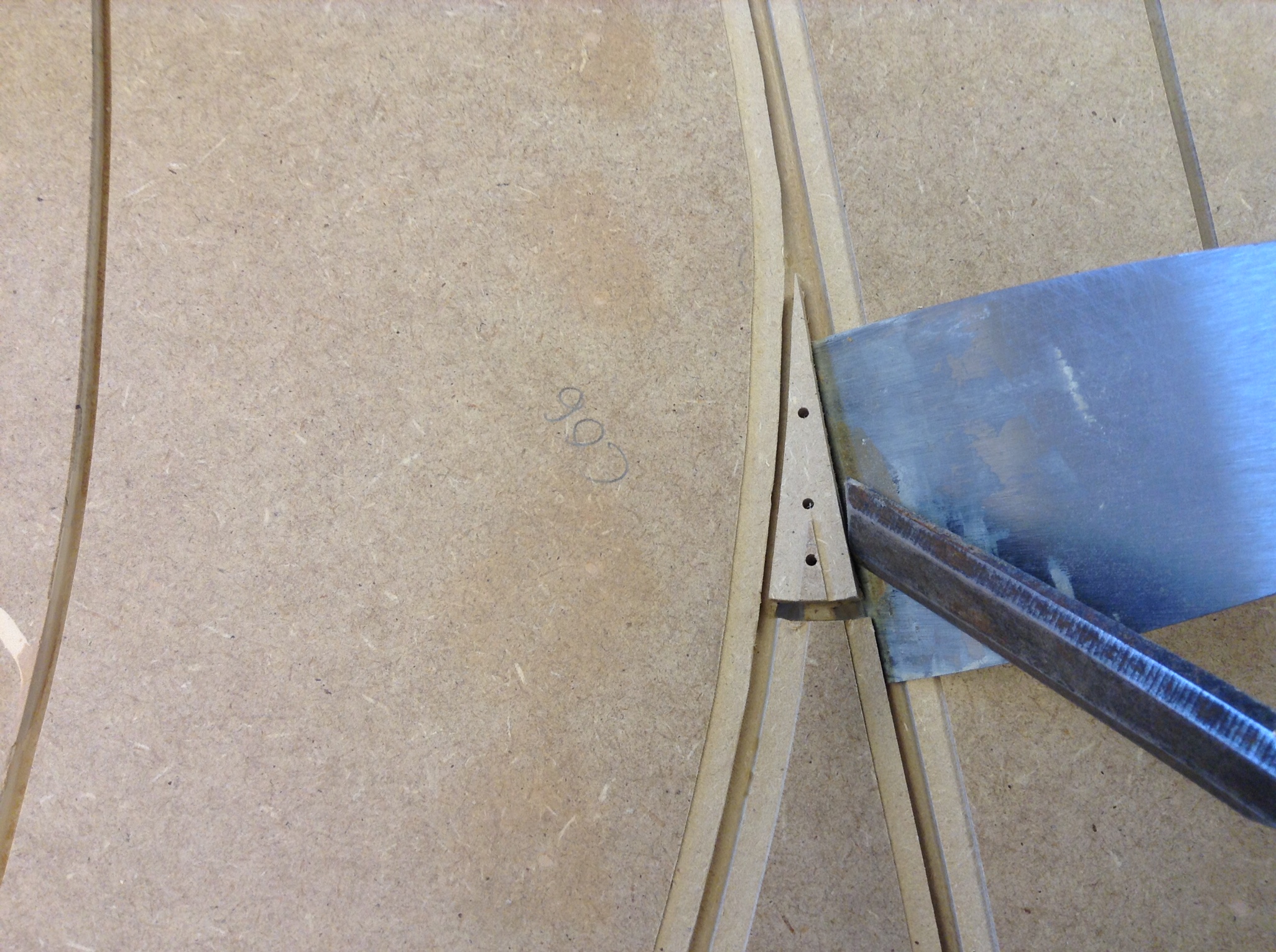
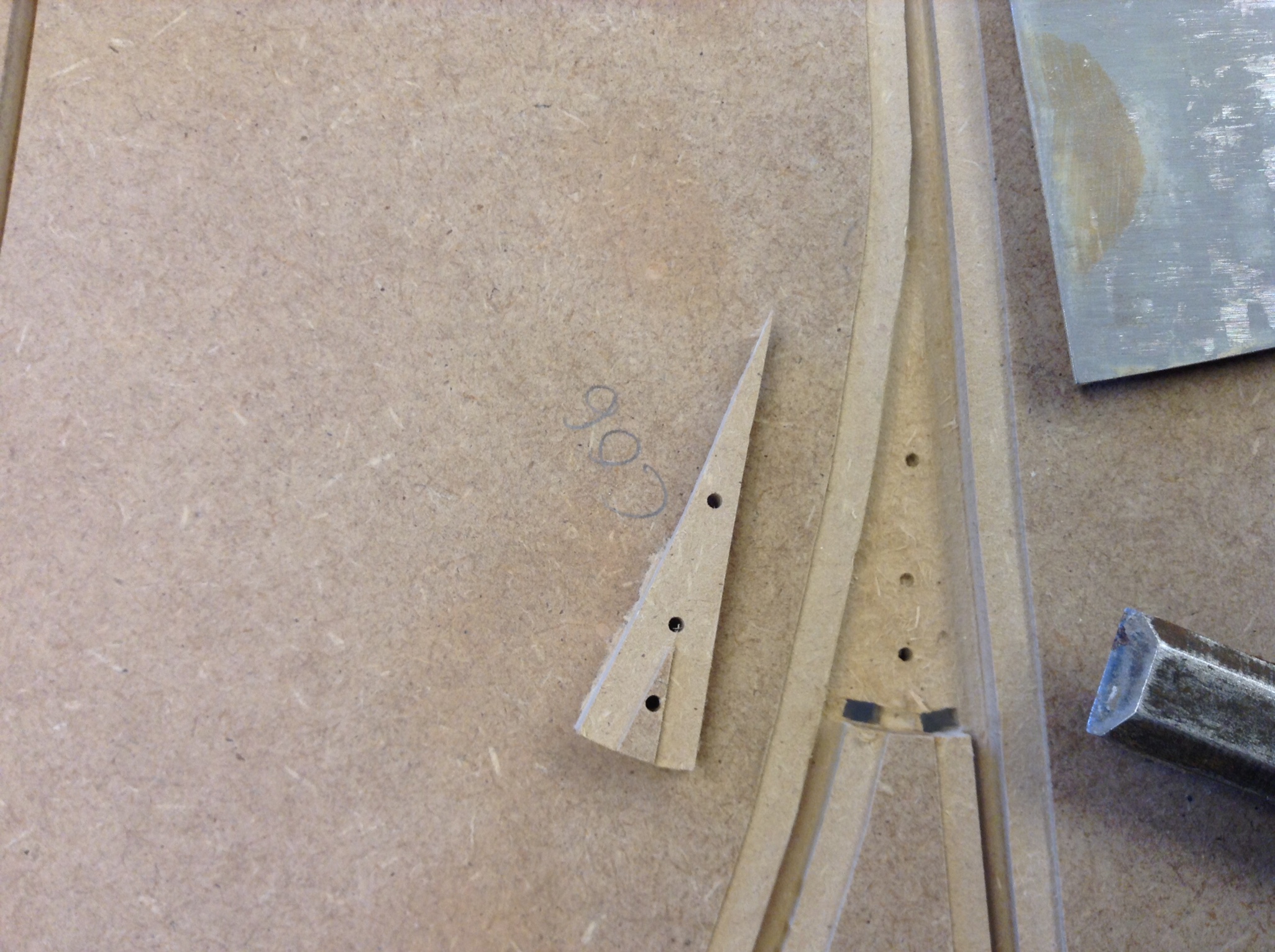
Customized flipper
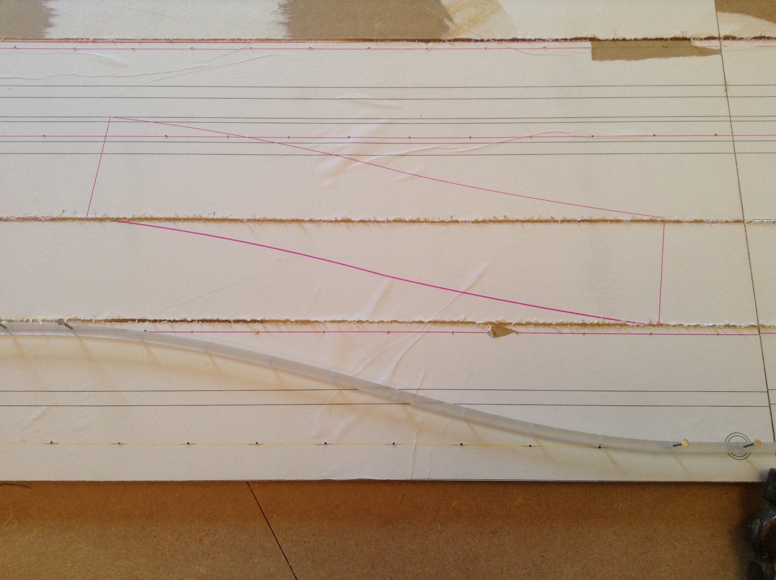
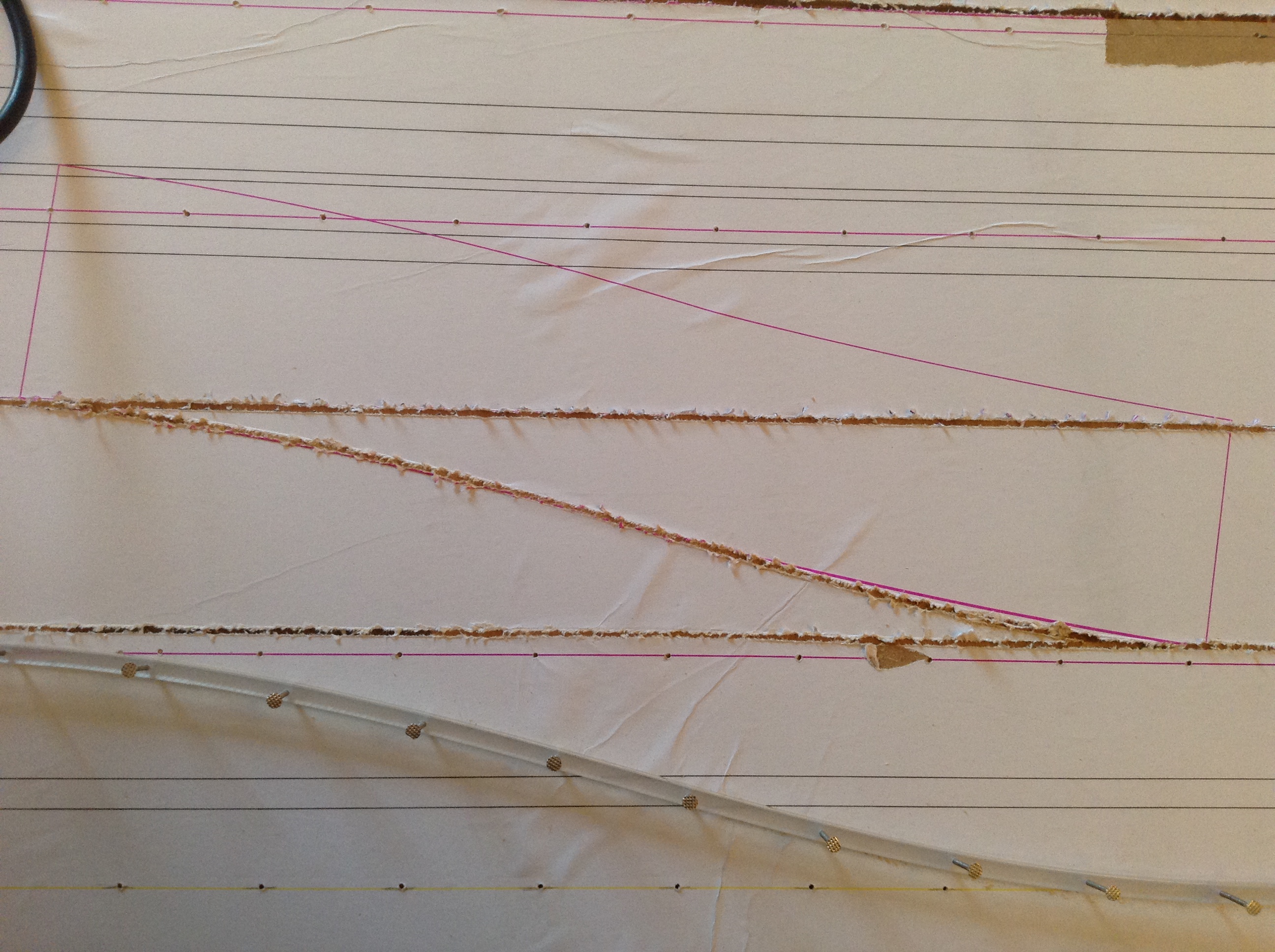
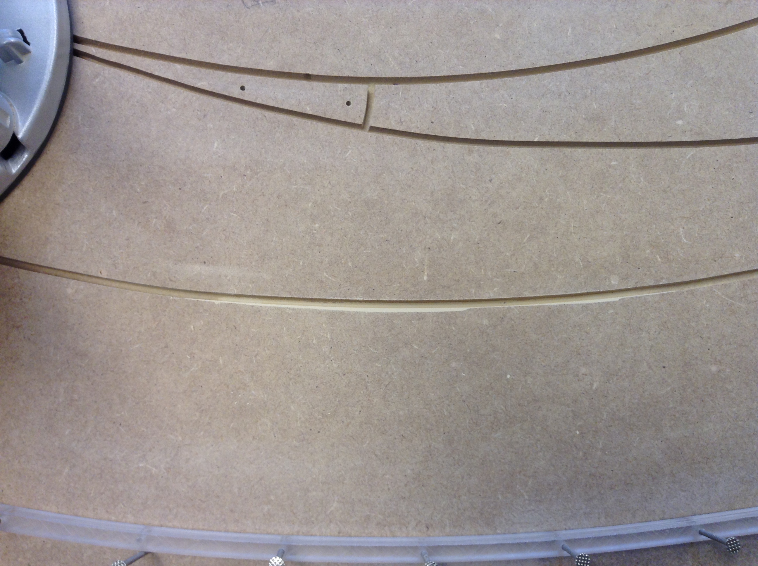
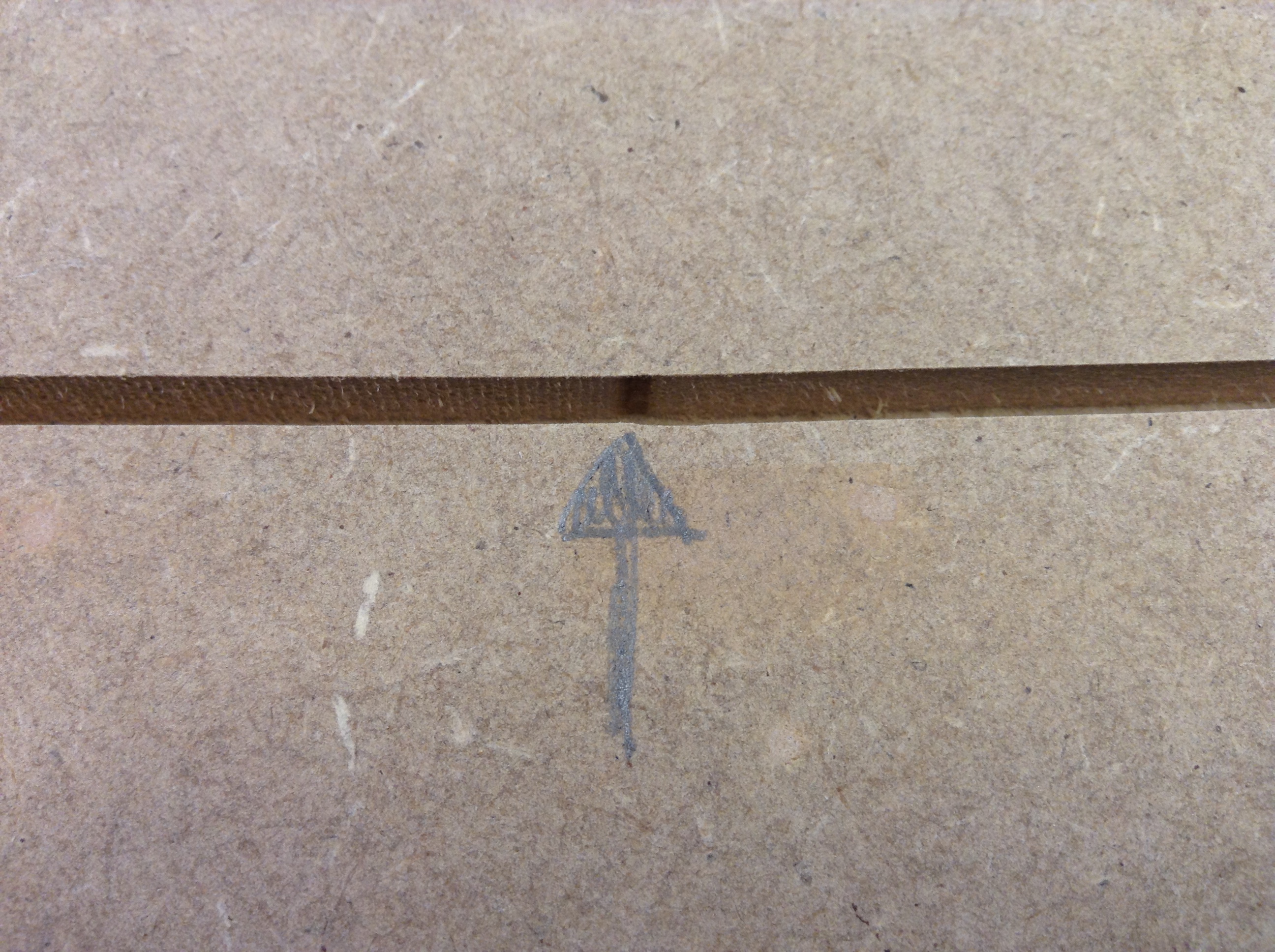
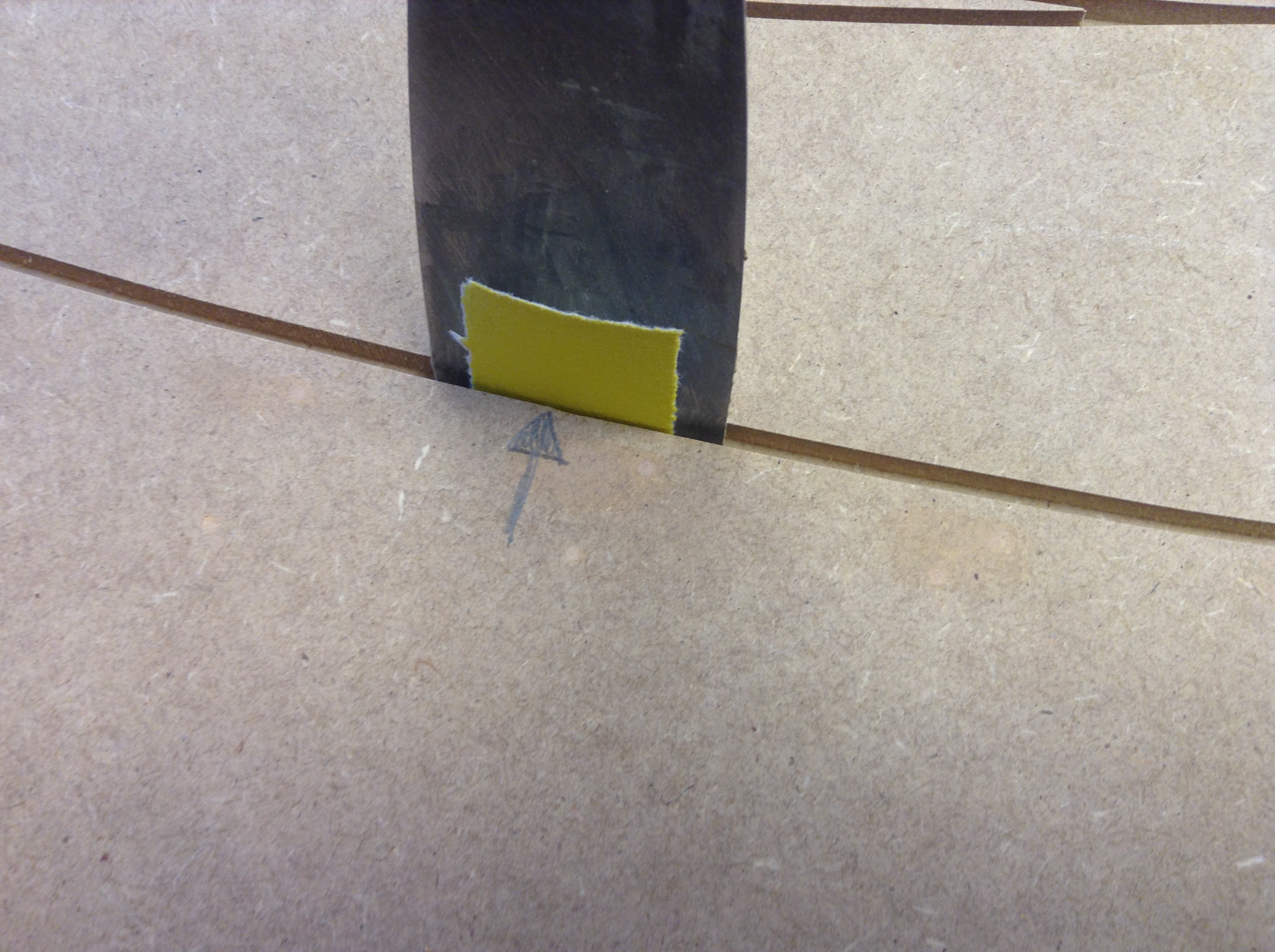
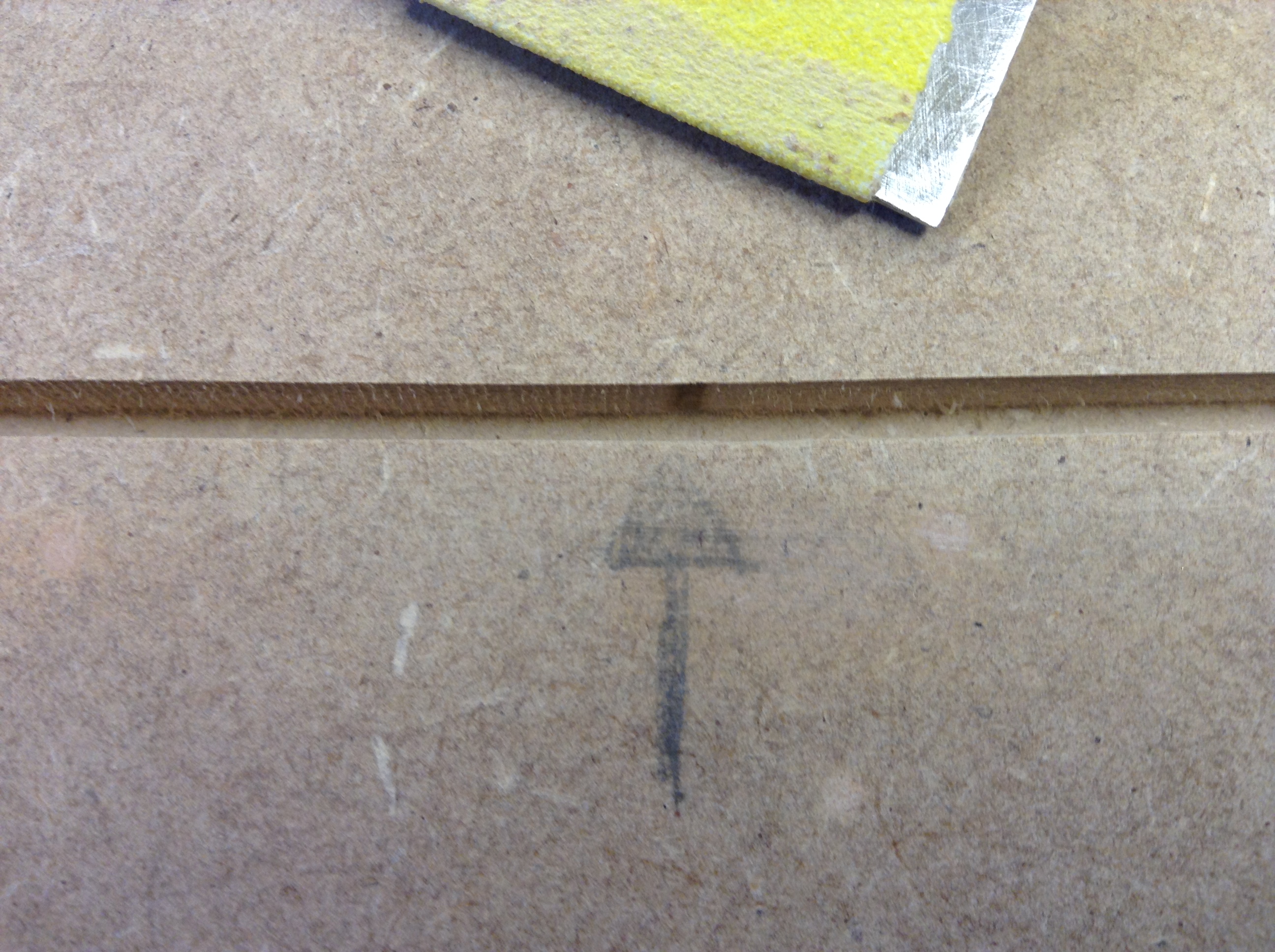
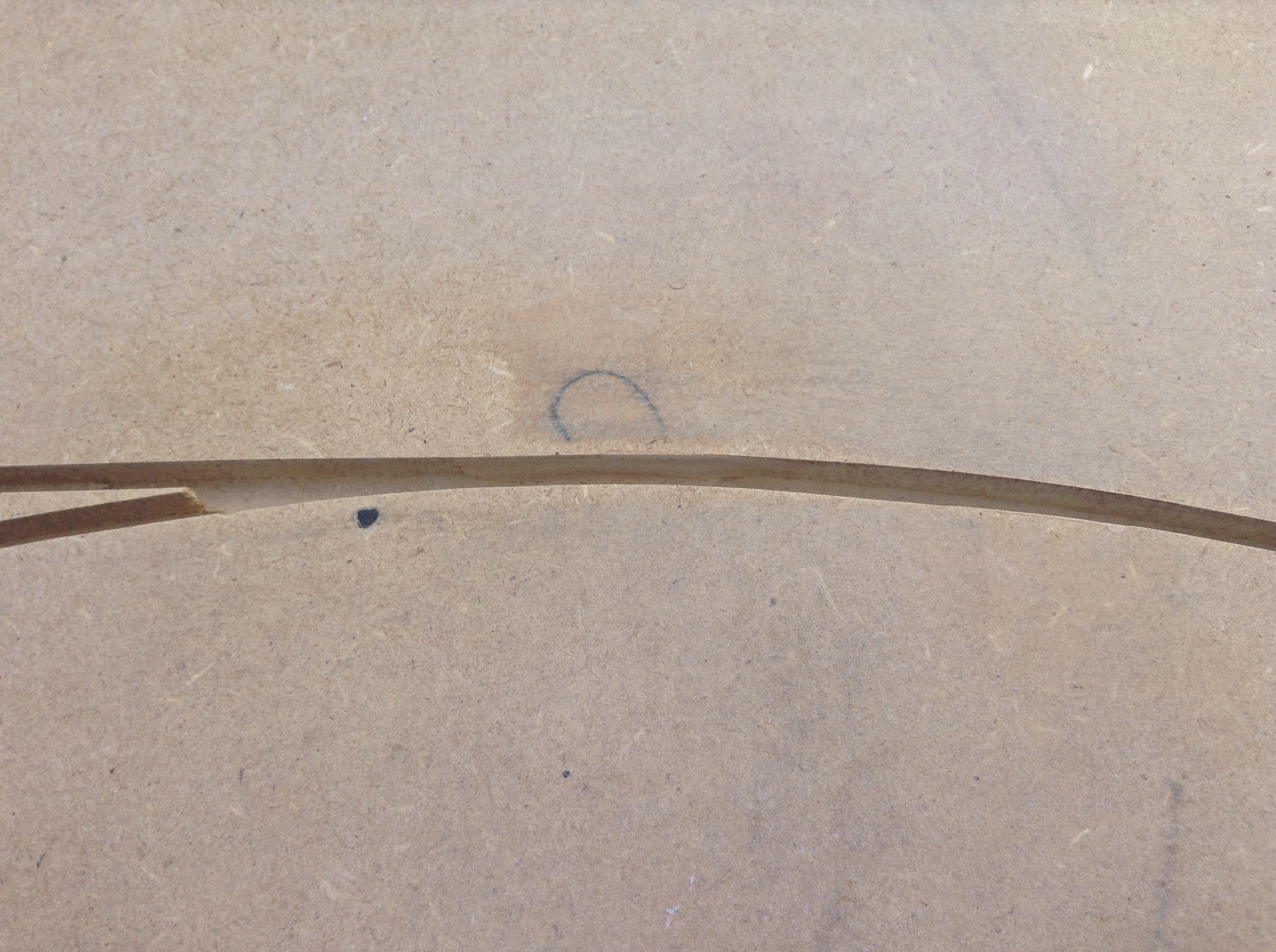
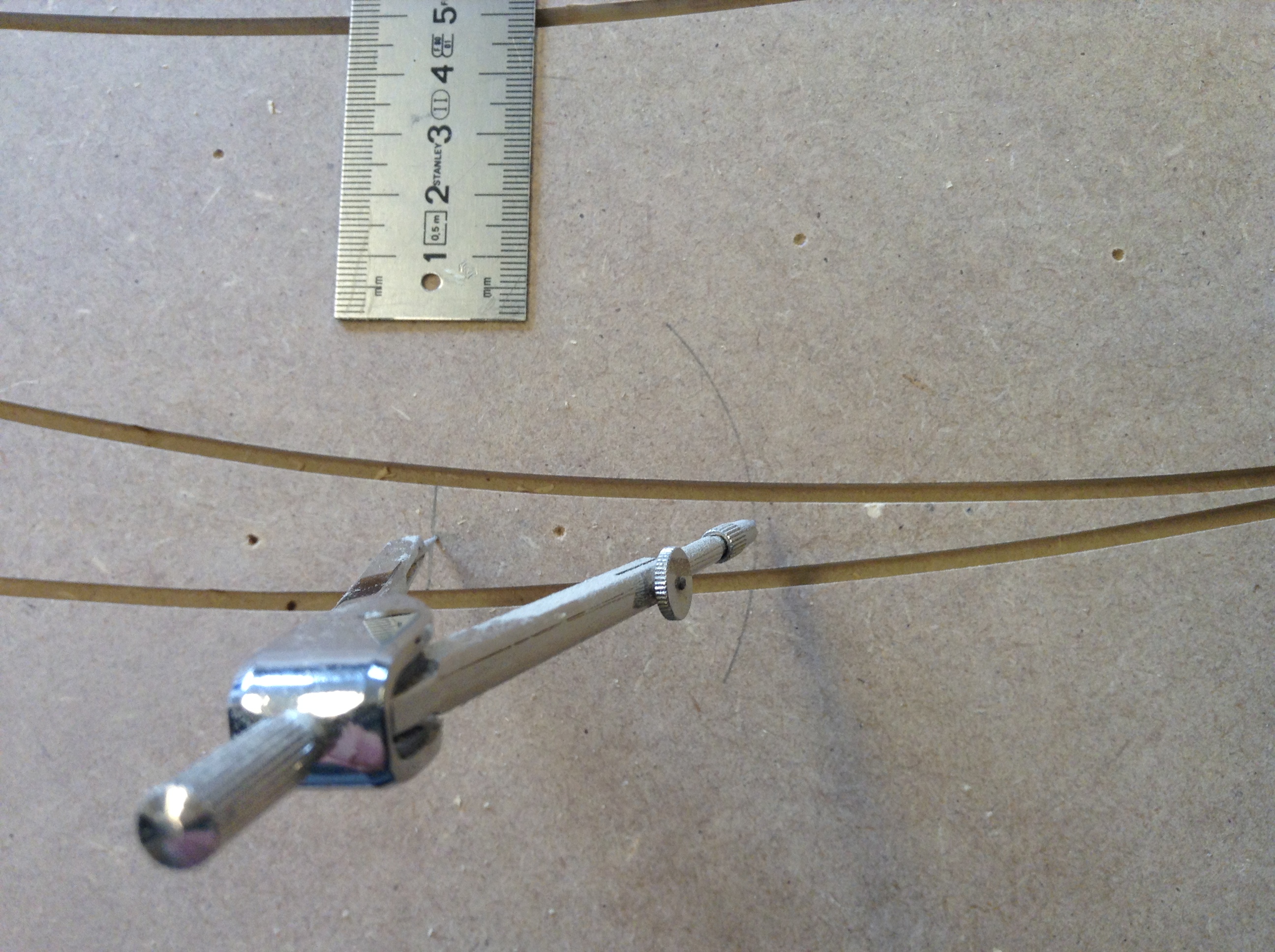
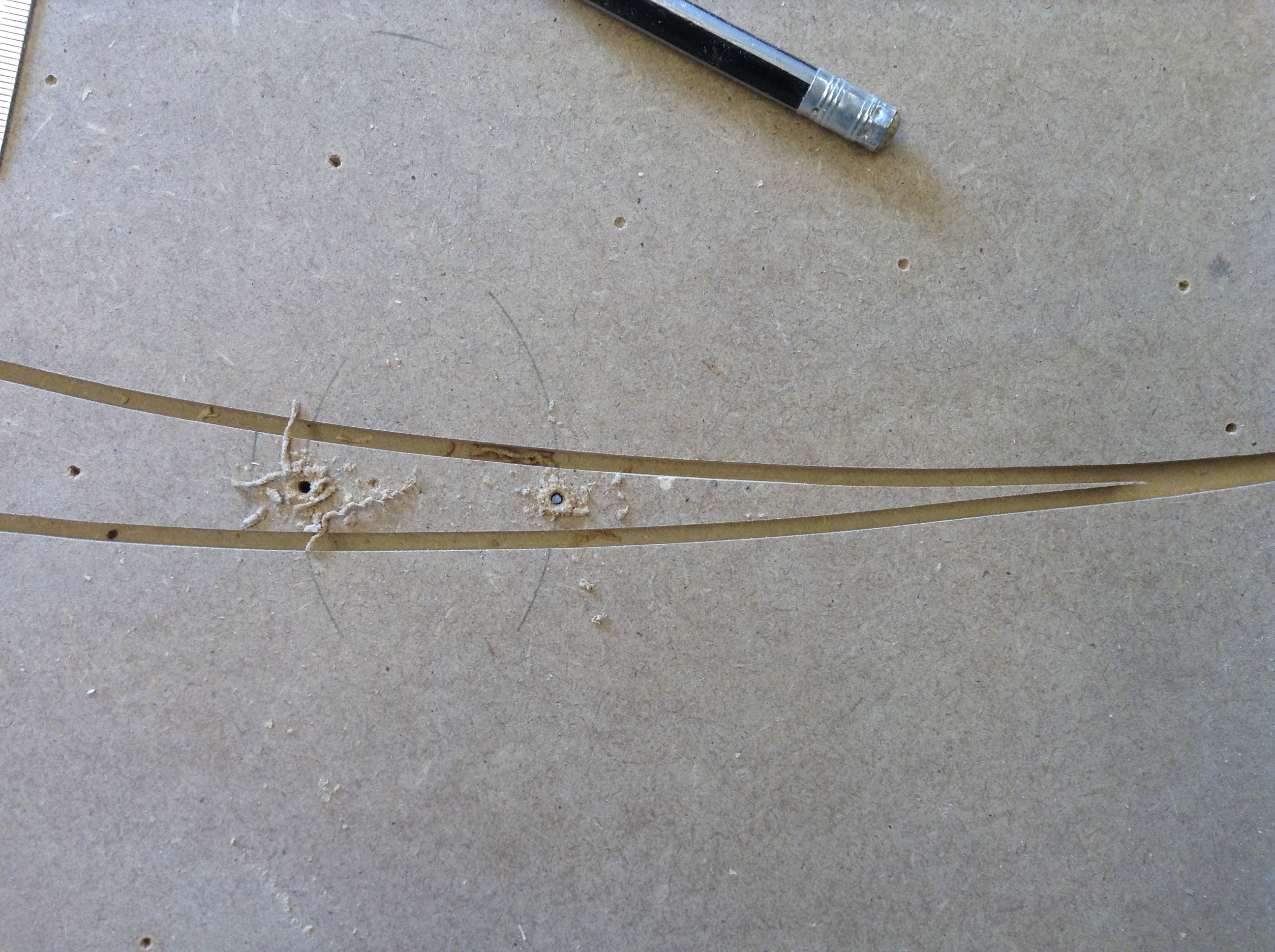
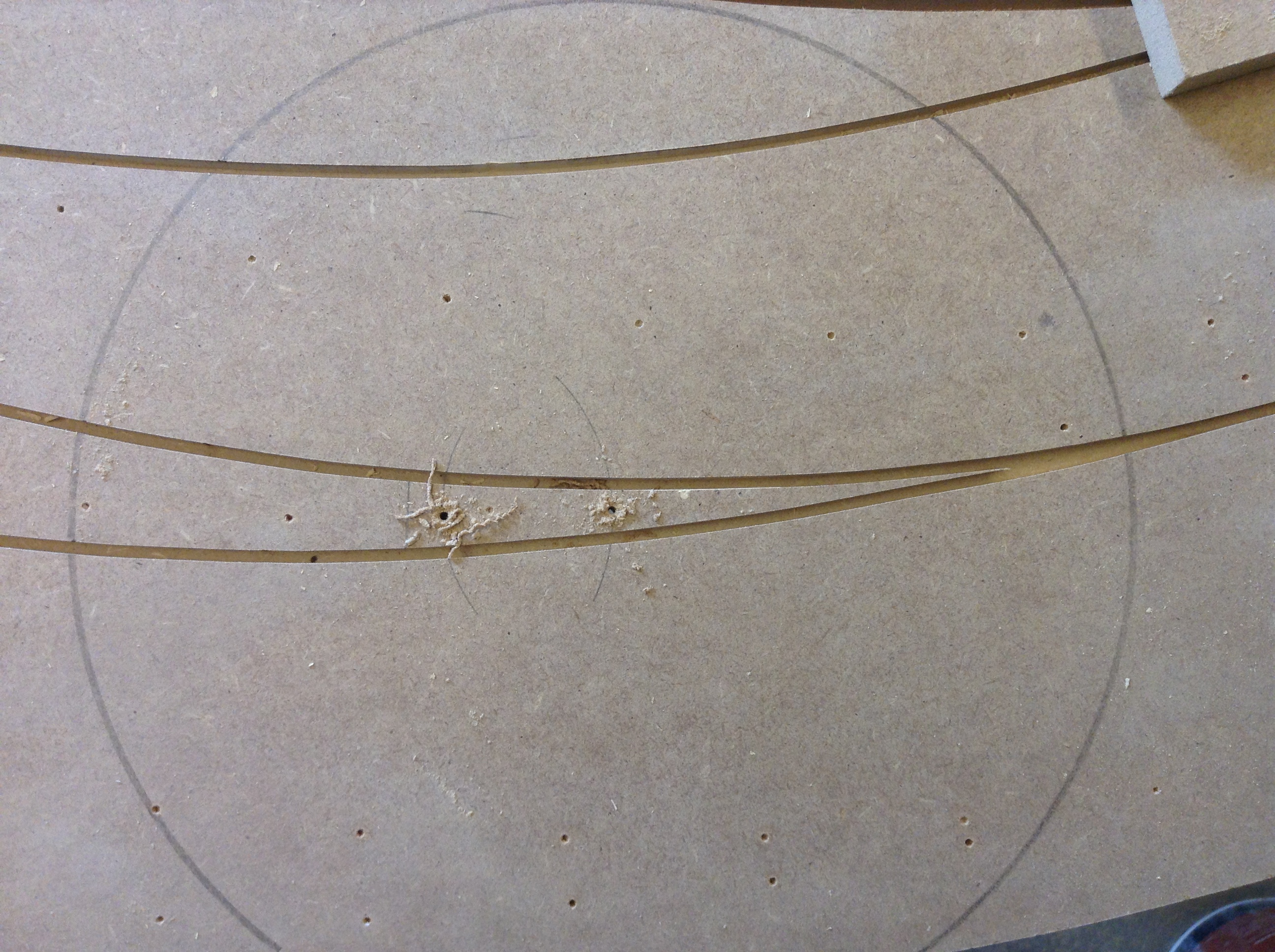
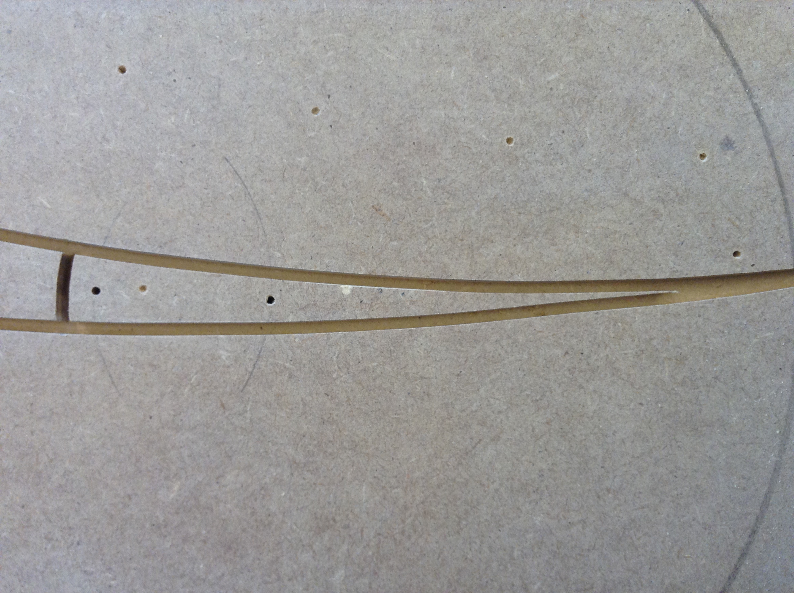
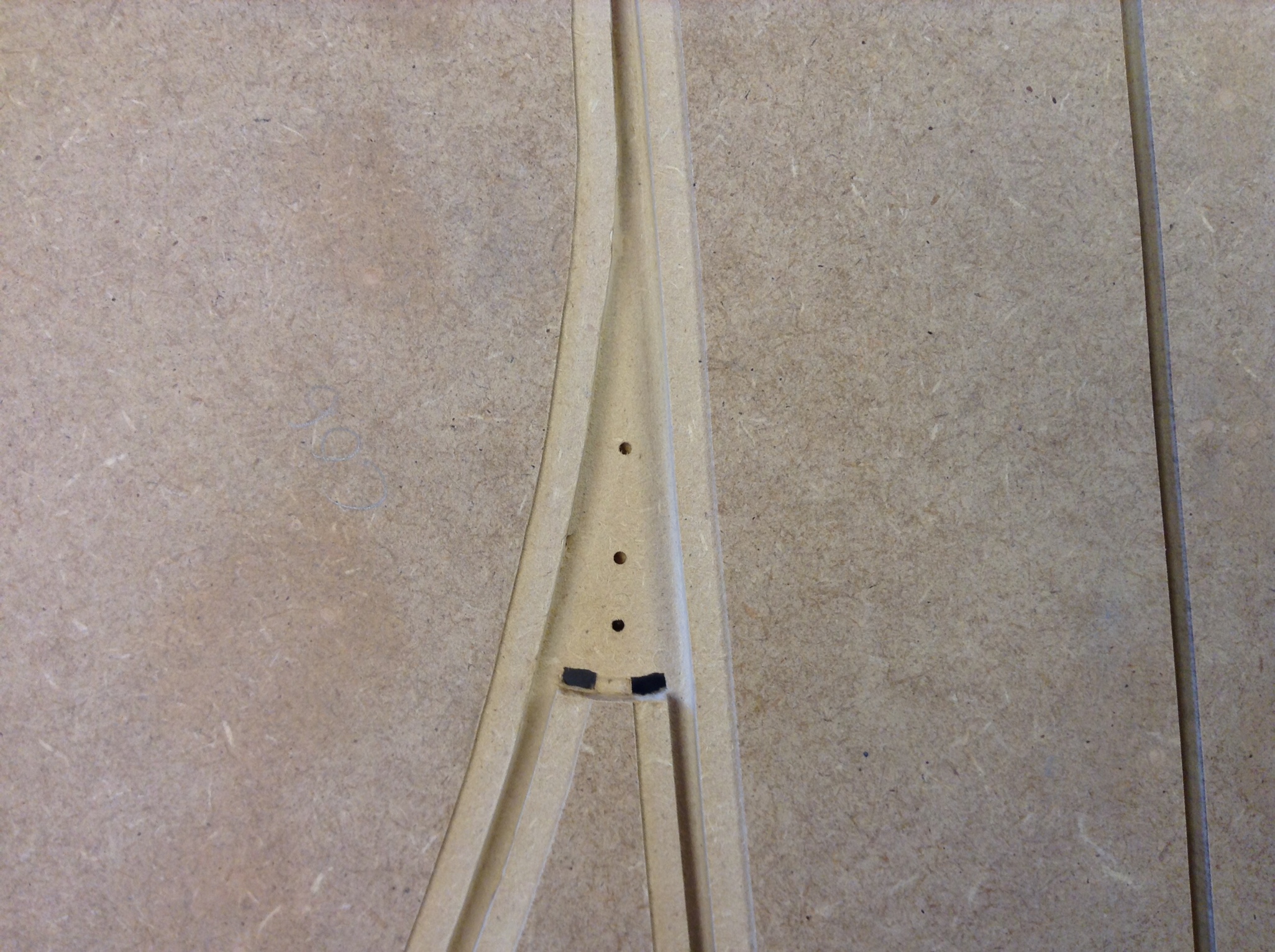
At the exact point where the distance between the slots, just after the IN flippers and before the OUT flippers, are 16 mm, I have to make a 3 mm cut to separate the flippers from the braids. (Figure 1)
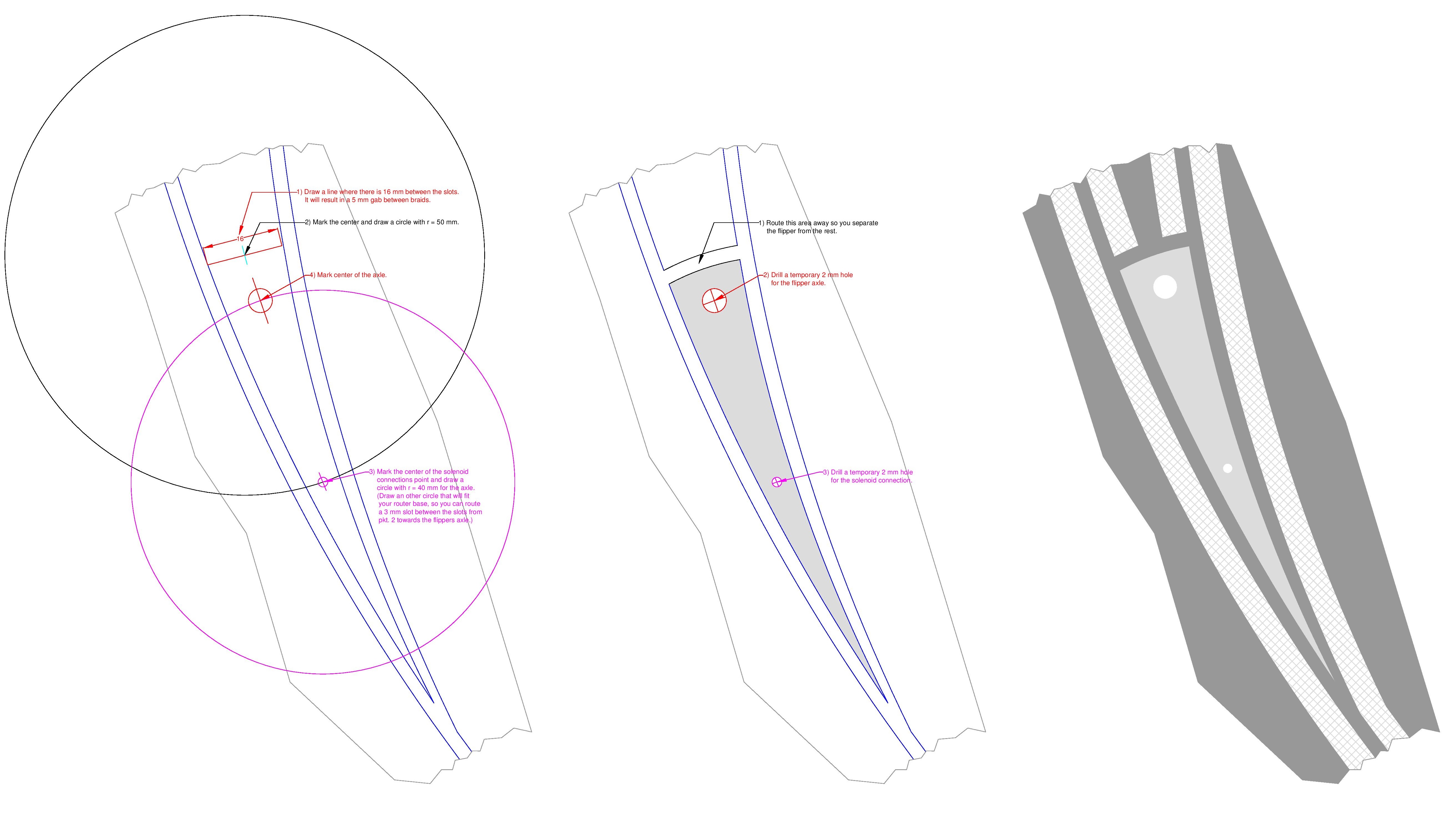
Figure 1: Measuring LC flipper
As you can see on figure 1, I also have to mark and drill two 2 mm temporary holes on each flipper, where I want the axle and solenoid connection point, I will drill the holes to the exact size later.
Room for braid
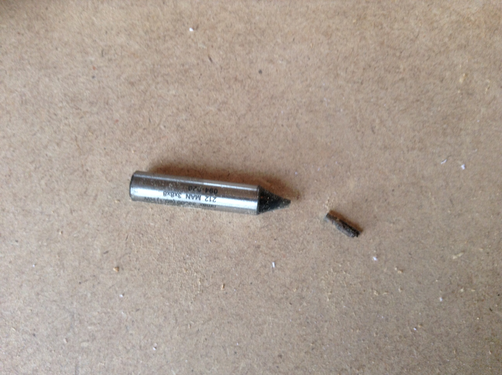
You can buy special router bits for the braid routing, with a guide in the same size as your slot. As the poor soul I am, I choose to make my own. I placed a 14 mm standard bit in a lathe, drilled a hole in the center of it, cut a M3 thread and mounted a piece of a M3 bolt secured by a drop of Loctite 270.
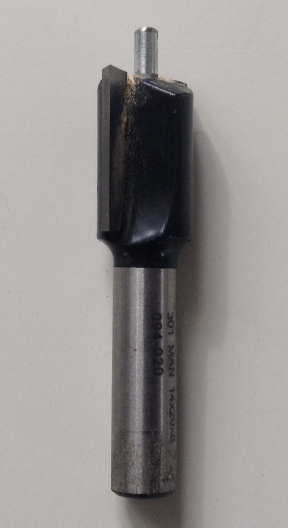
I route in a depth of 1 mm and it’s quite an easy job to route with the guided bit and the result is very nice I think.
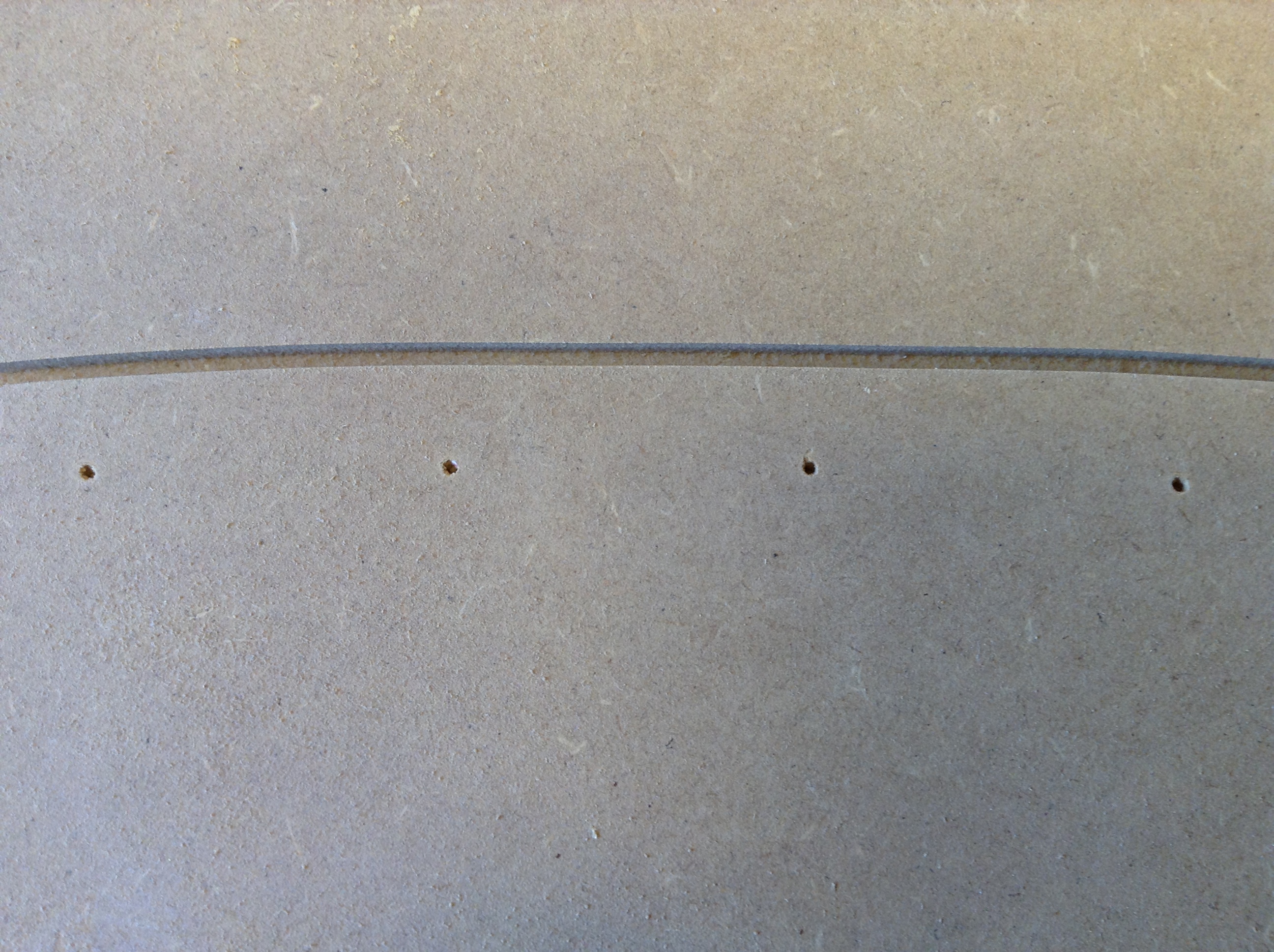
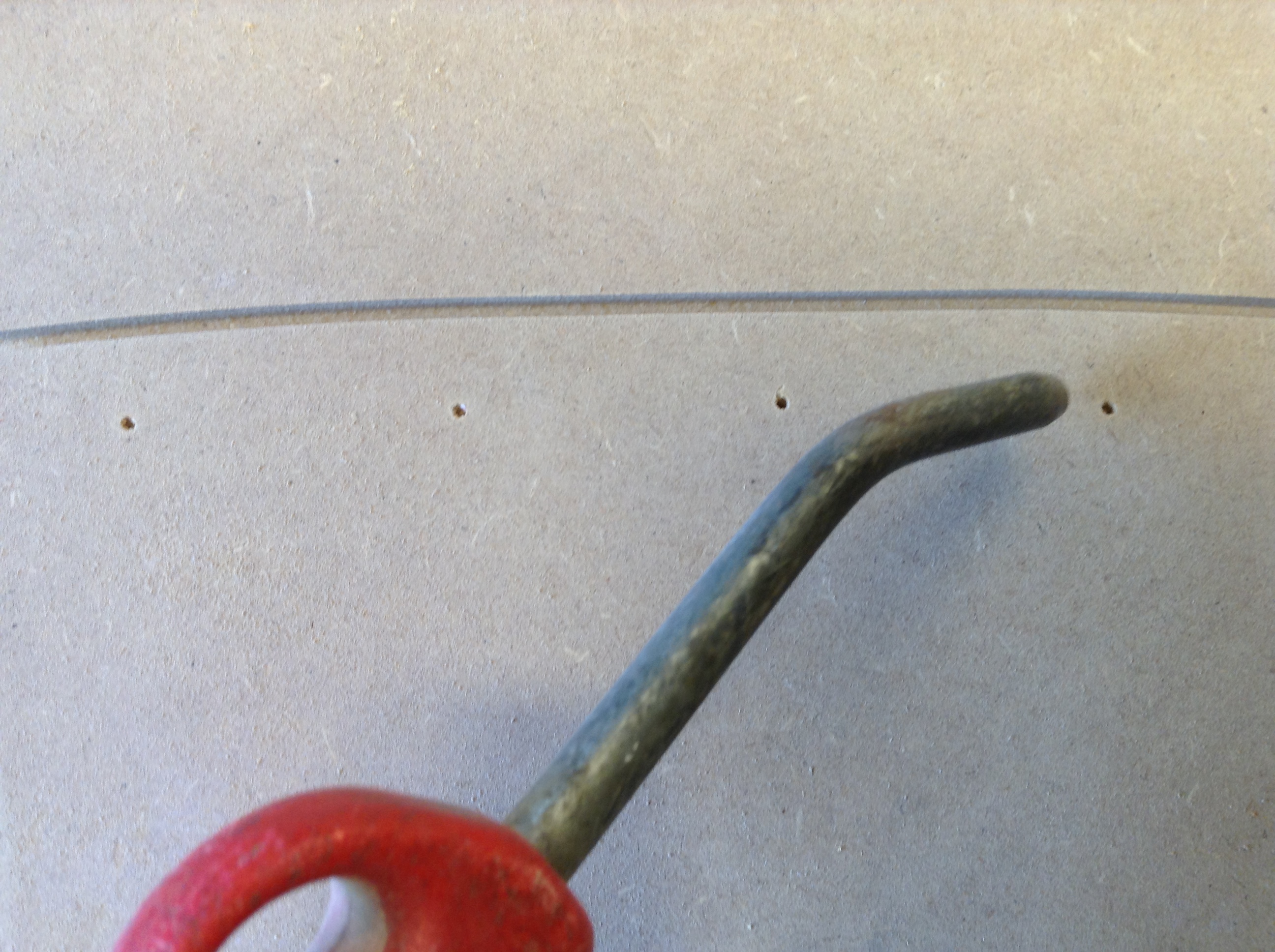
At each flipper I drill two series of 3 mm holes through the MDF for the braid connections and grind it with a small coating file to make nice 90º corners.
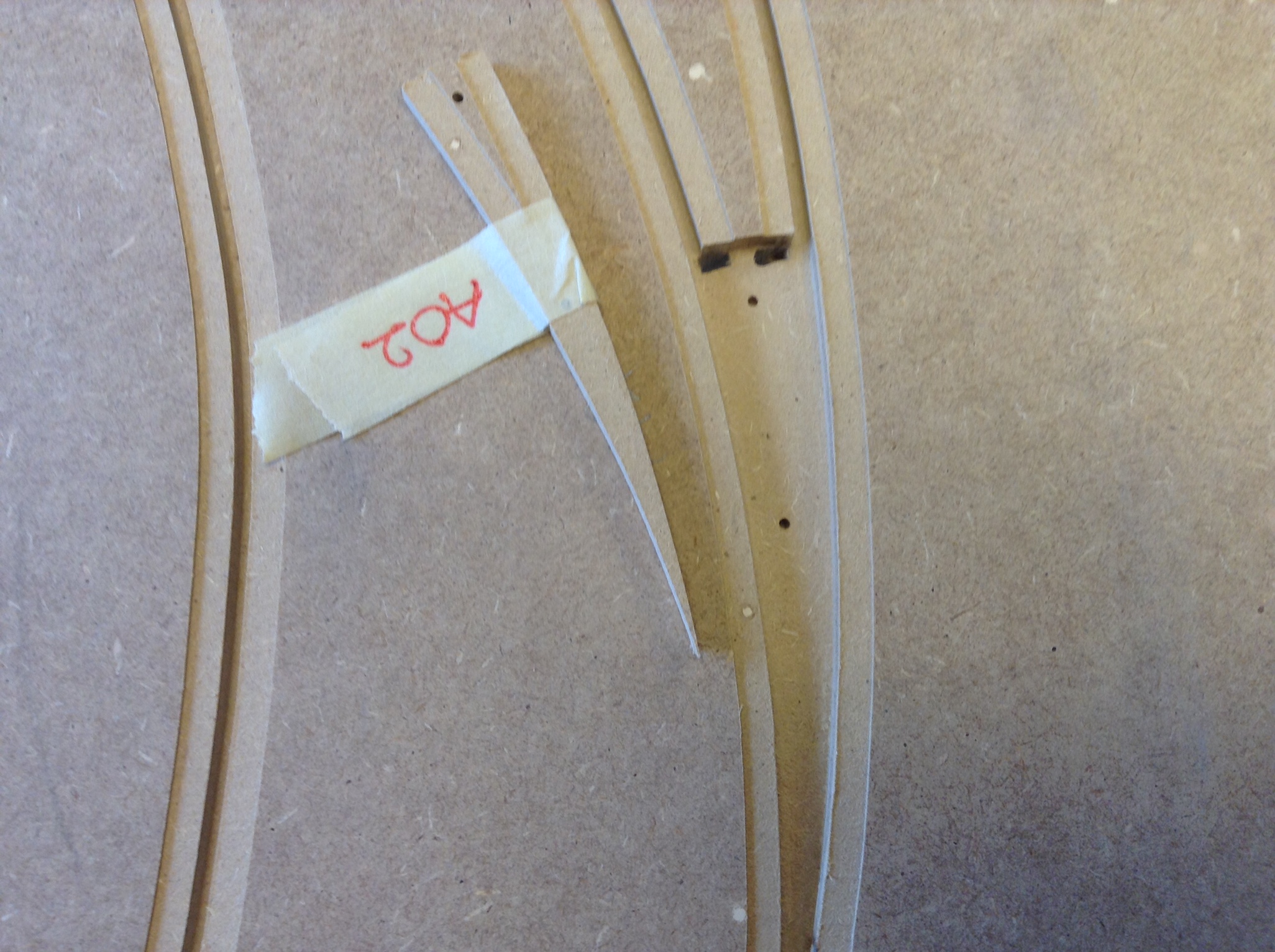
Space for the LC flipper
I will now remove the “MDF LC flippers”, I simply tilt them of and thereby have an exact copy.
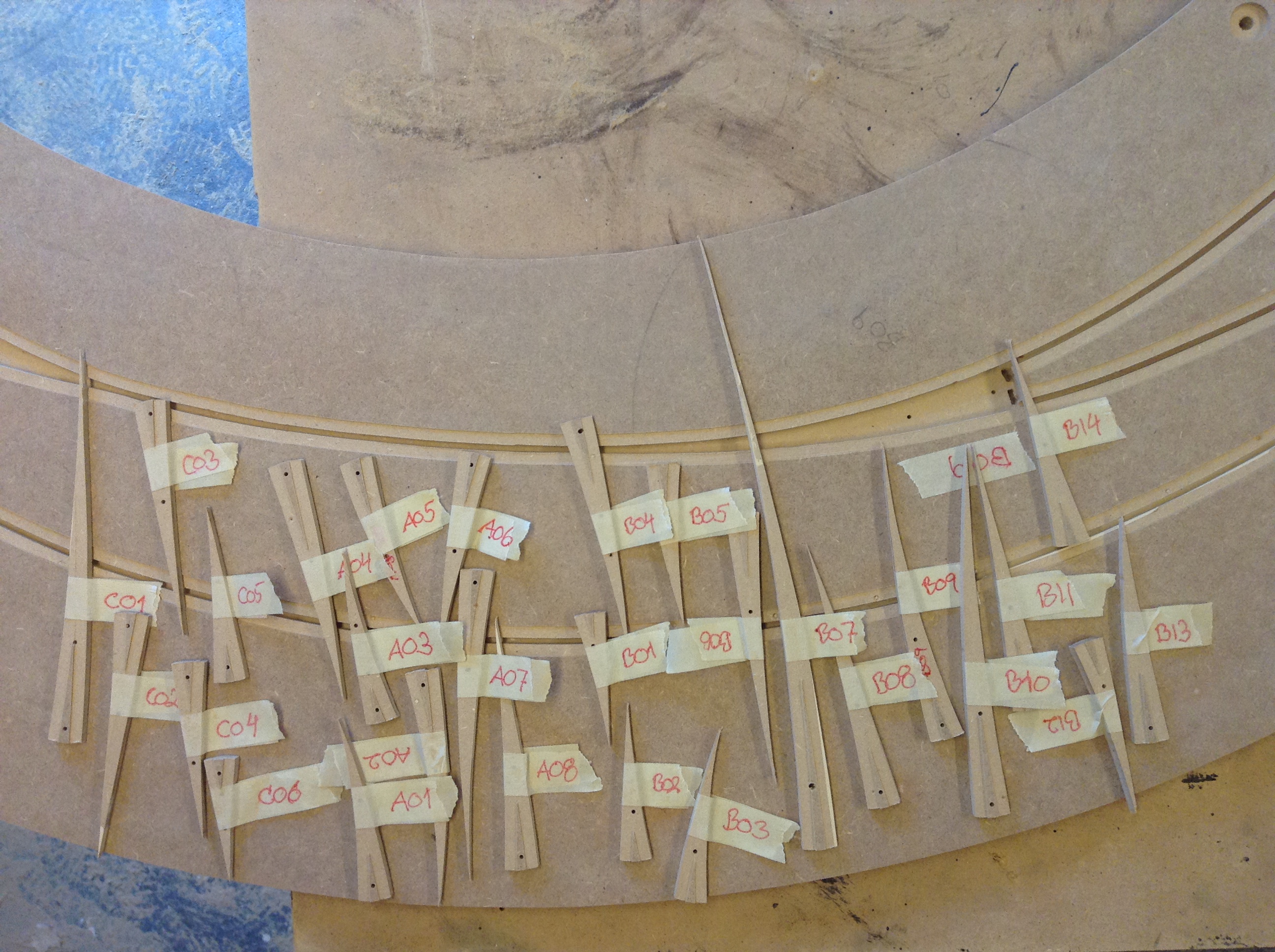
I will later make 5 mm flippers out of a aluminium. See the further manufacture of LC‘ in the submenu: Space for technique.