
In this section I will route space for slotted optical switches, solenoids, electronic, etc. on the back side of the track and fabrikate the active and passive flippers. I have chosen to raise the track 10 mm from the MDF frame. The reason of that is, that I want space to incorporate and protect the electronics.
Scalextric Power Base
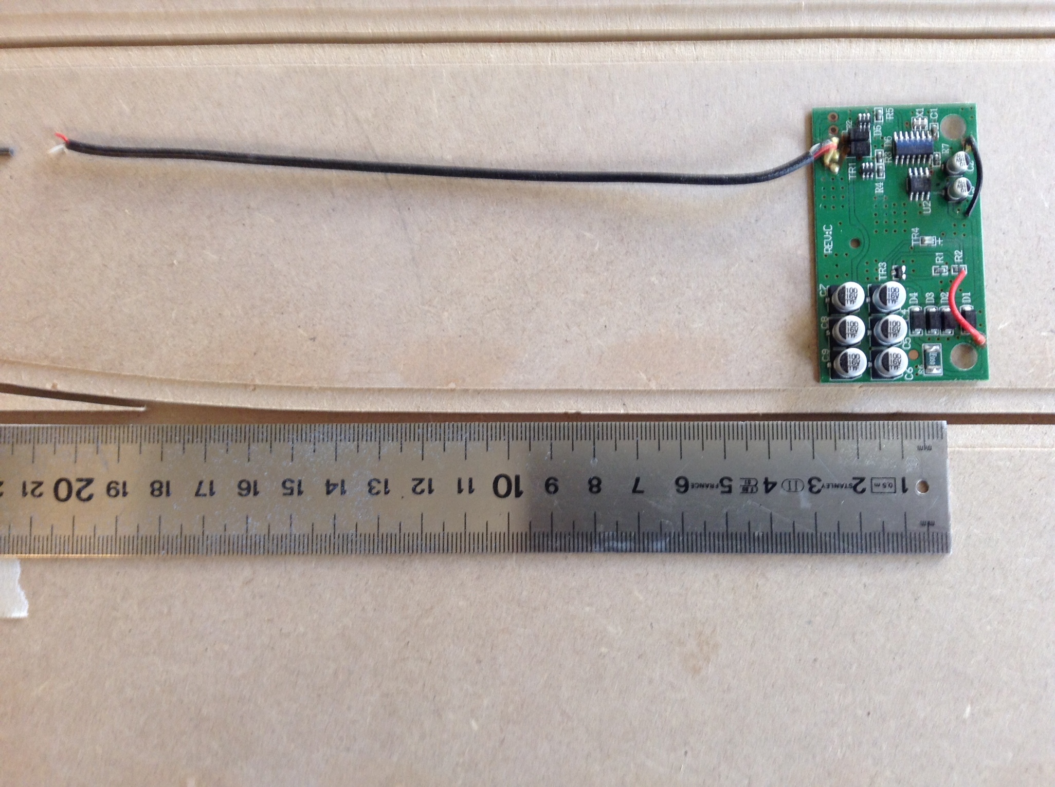
Where the Scalextric PB C7042 is located on the track, is the only area where the distance between the slots, have to be exactly 77 mm. There are two small strips of PCB‘s build-in the Scalextric PB rail. Just before the start/finish line there is a LED to identify the passing car and at the line it’s an optical switch that records the lab time.
I have cut the wires from the PB to the 2 PCB‘s and the wires to the rails. These will later be mounted to the PB by connectors.
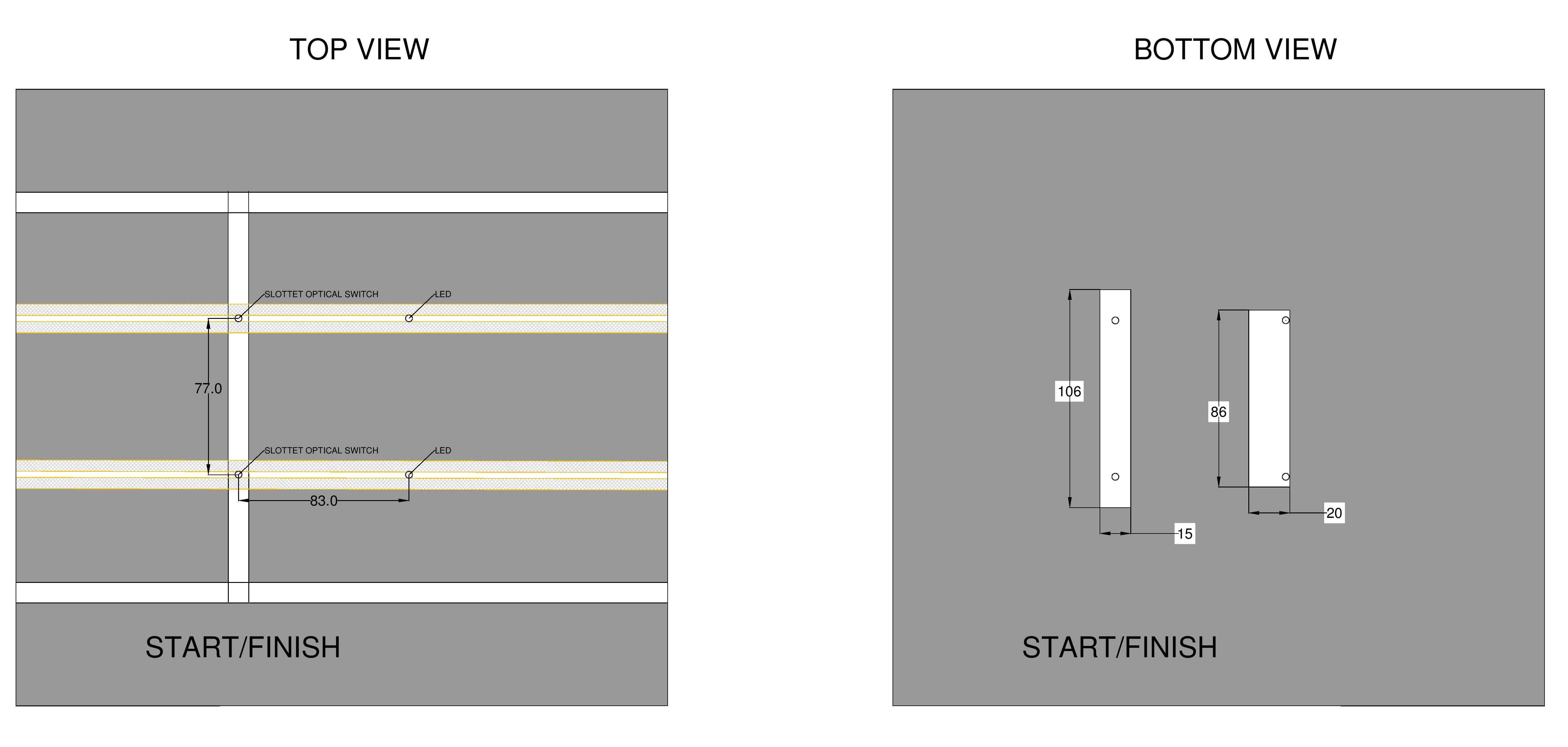
Figure 1: Scalextric Power Base
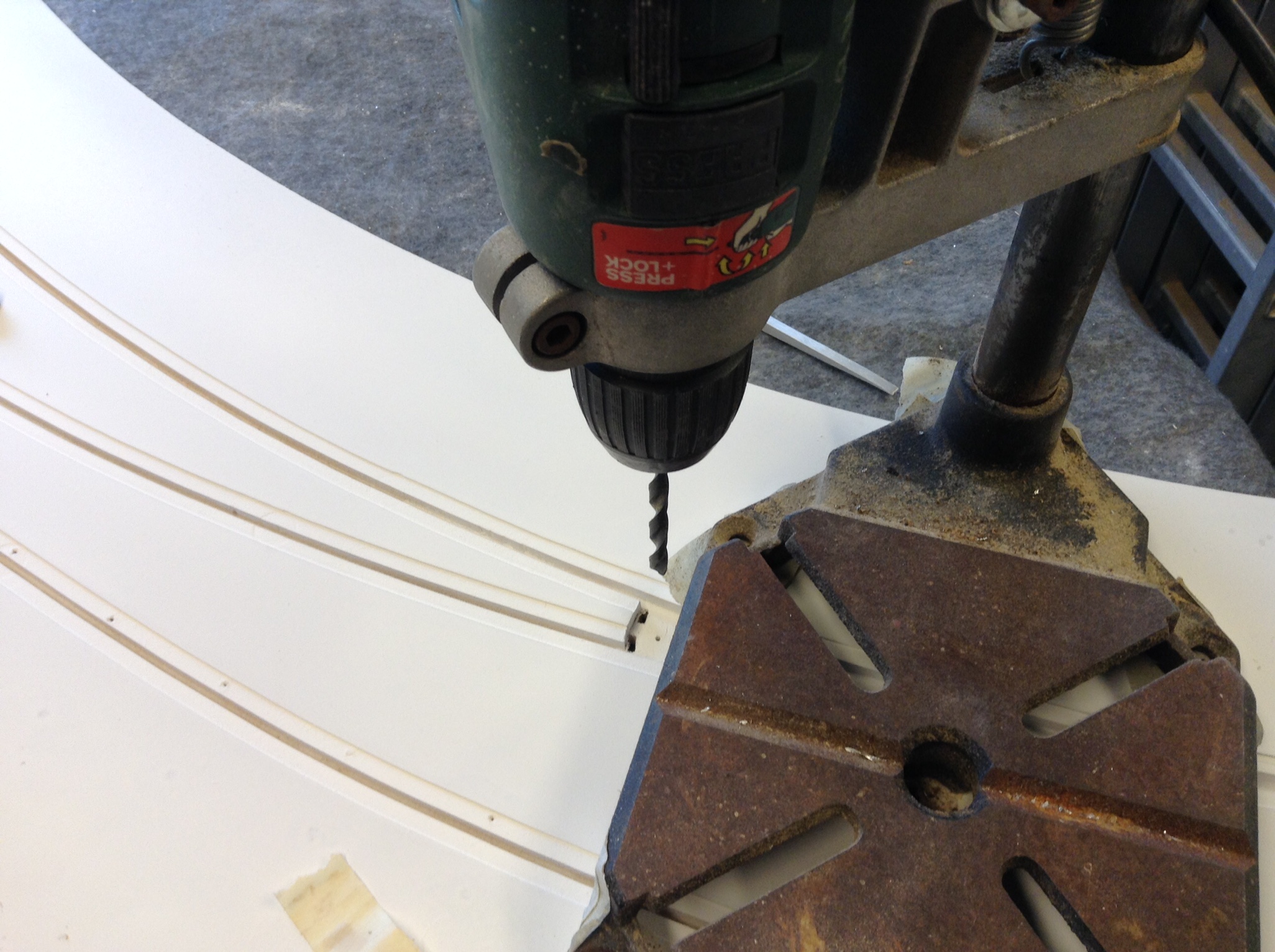
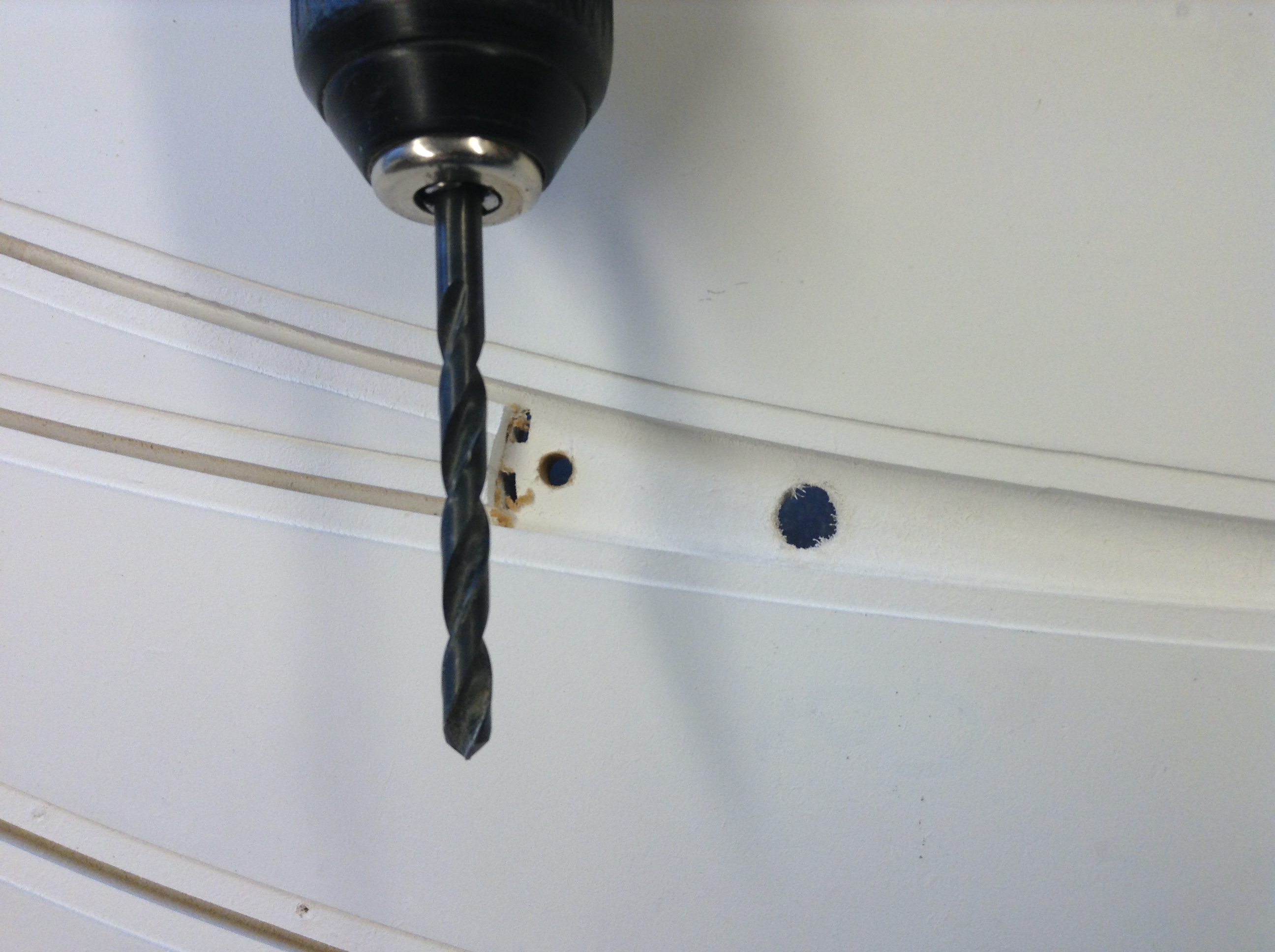
Slotted optical switches
This section covers both the procedure for SOS‘s controlling the anti collision system and the “live” passive OUT flippers.
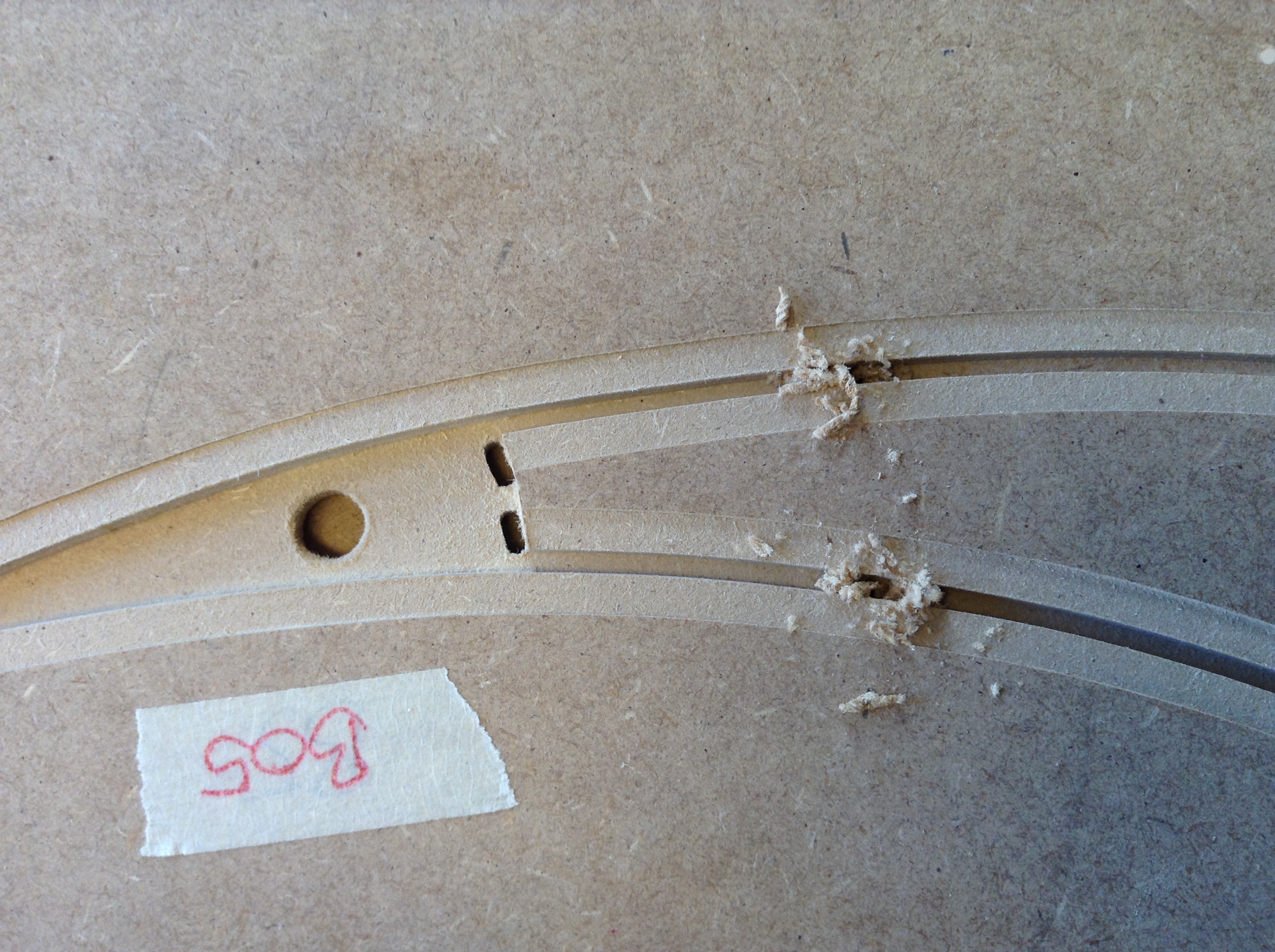
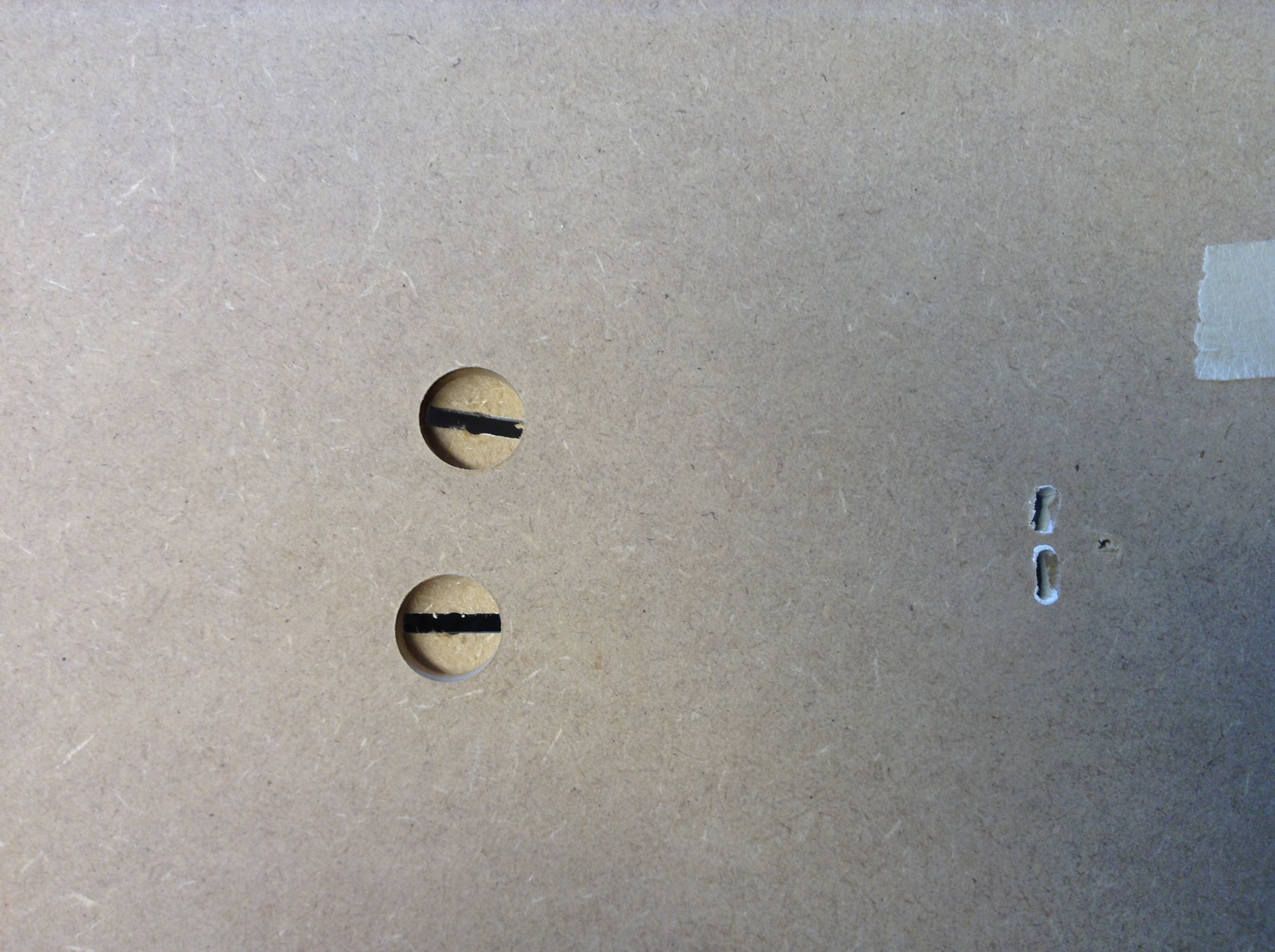
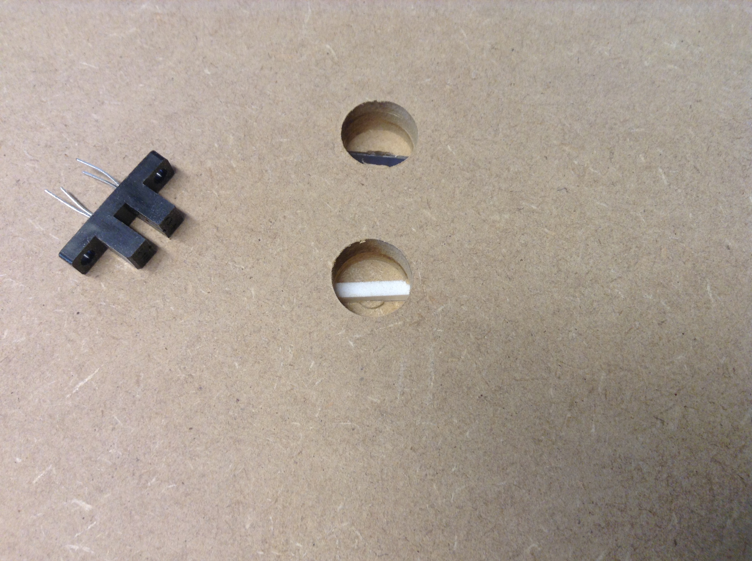
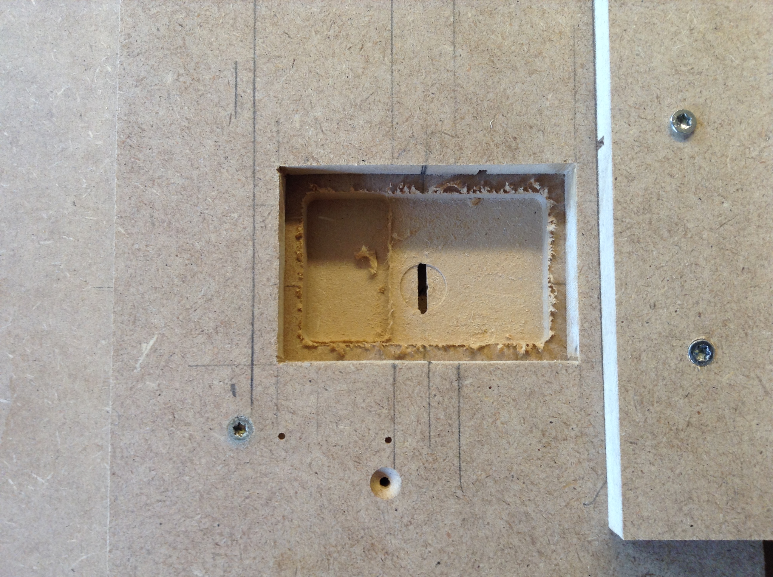
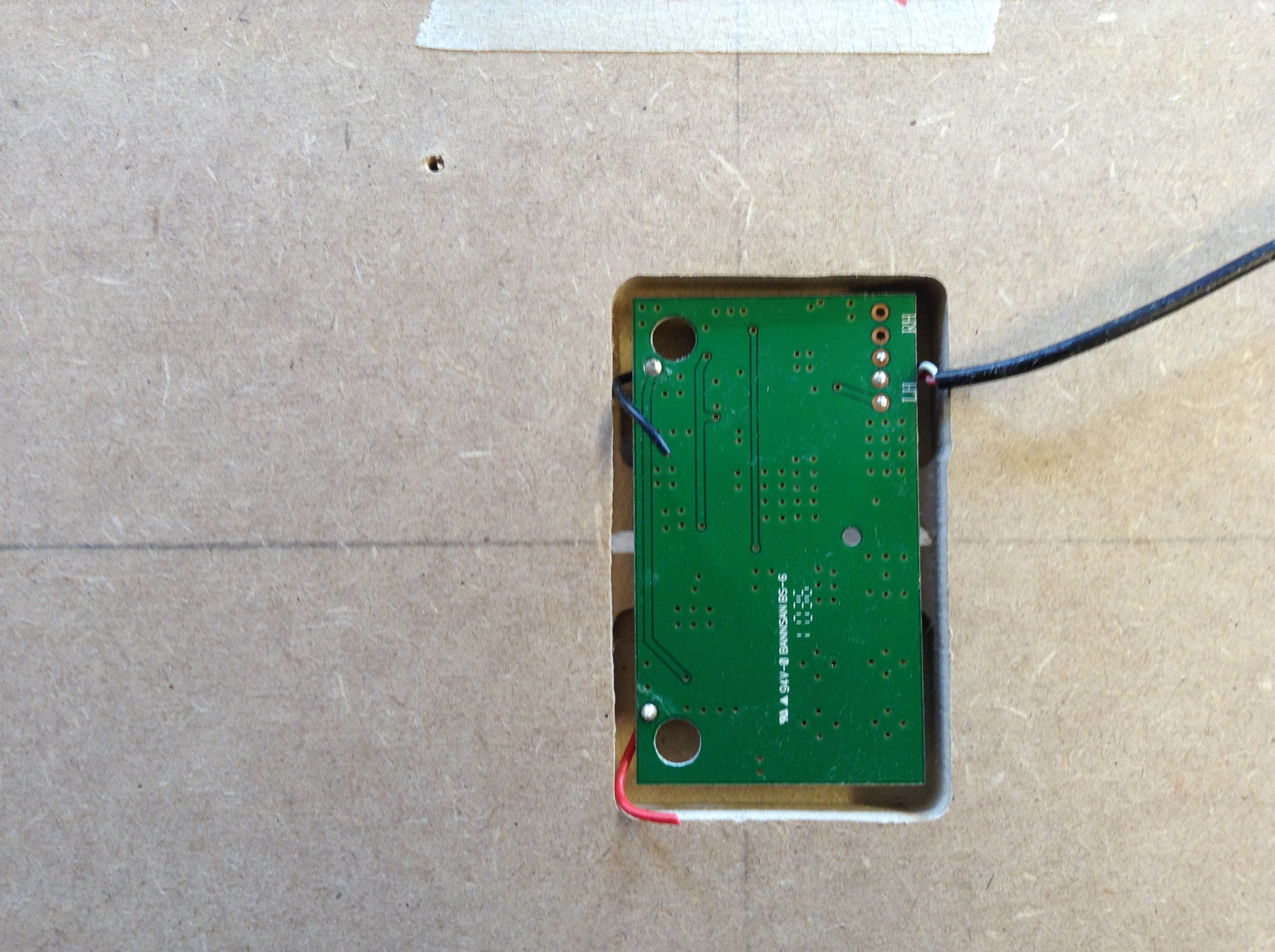
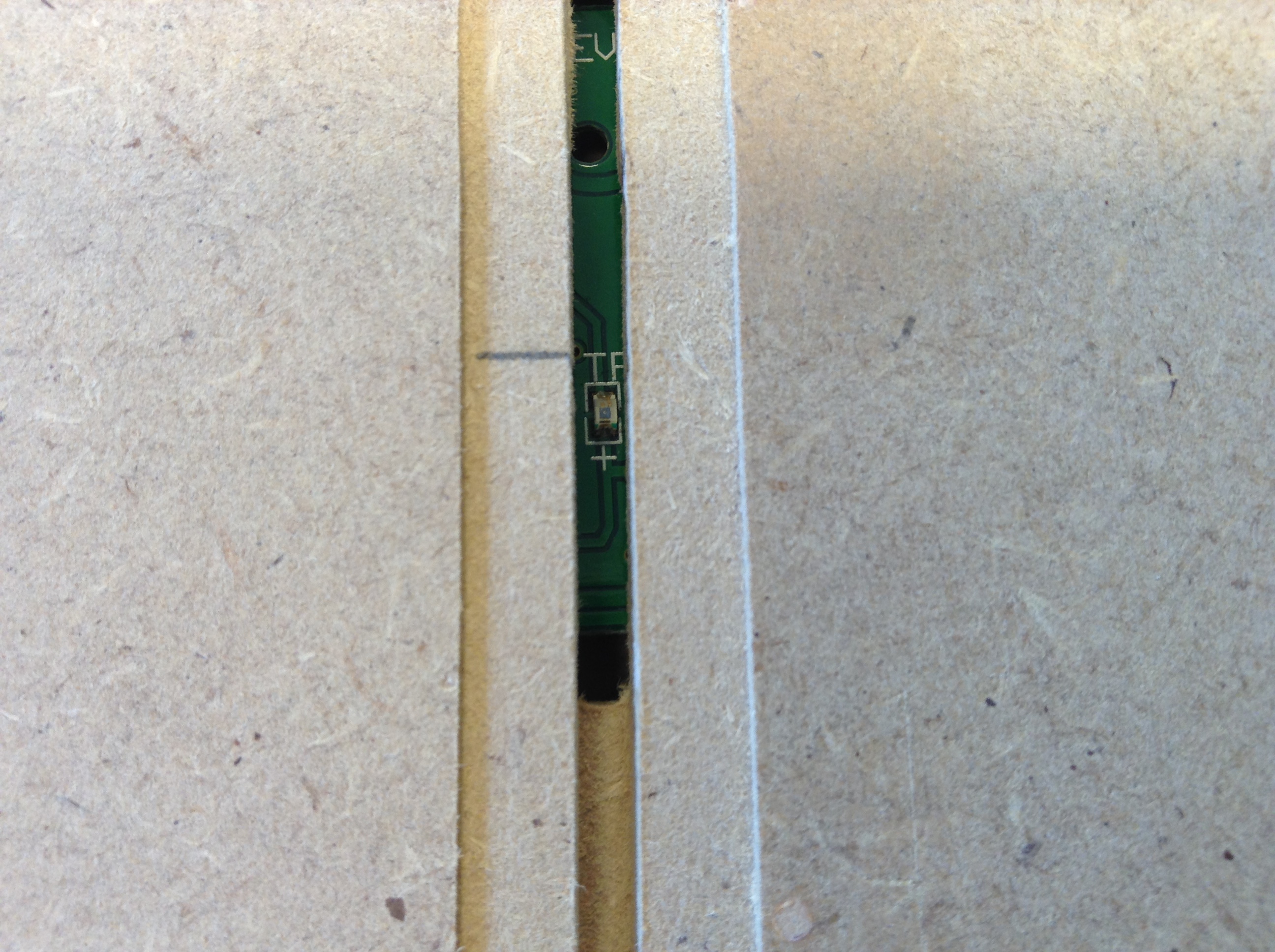
- Mark the location of all slotted optical switches and drill a 3 mm hole in the slot through the MDF.
- With the braid router¹, route a 10 mm deep hole from the back side. When routed there will be 1 mm MDF left underneath the braid.
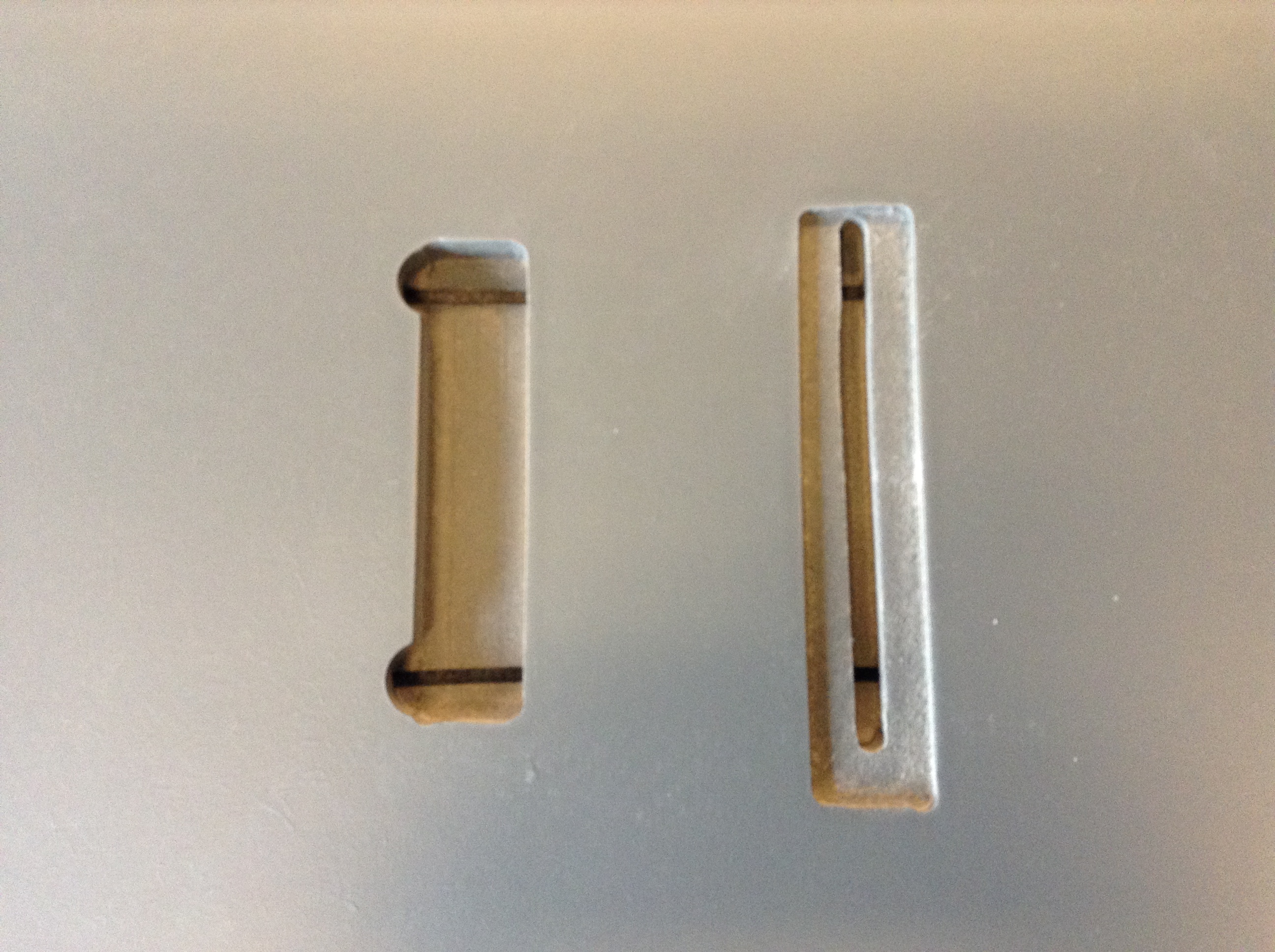
- Mount a small piece of 3 mm MDF in the slot. The MDF piece is visible through the 14 mm hole from the back side.
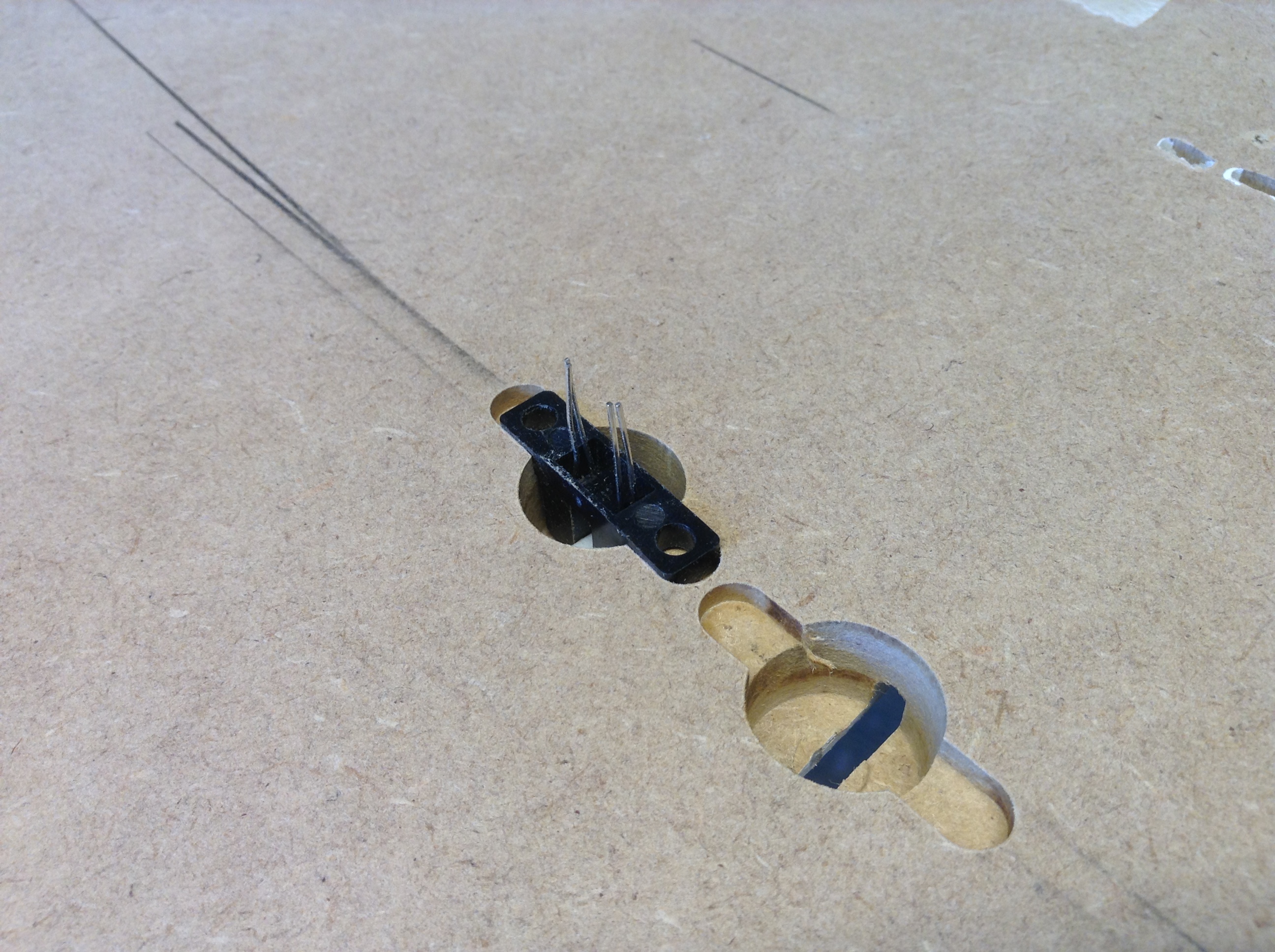
- Place the gab of the slotted optical switch, so it fits in with the piece of 3 mm MDF.
- Mark the “wings” on the optical switch and route a 3 mm deep, 6 mm wide and 25 mm long slot in the same angle, so it fit flush with the surface of the MDF.
That was 1 out of 55 🙂
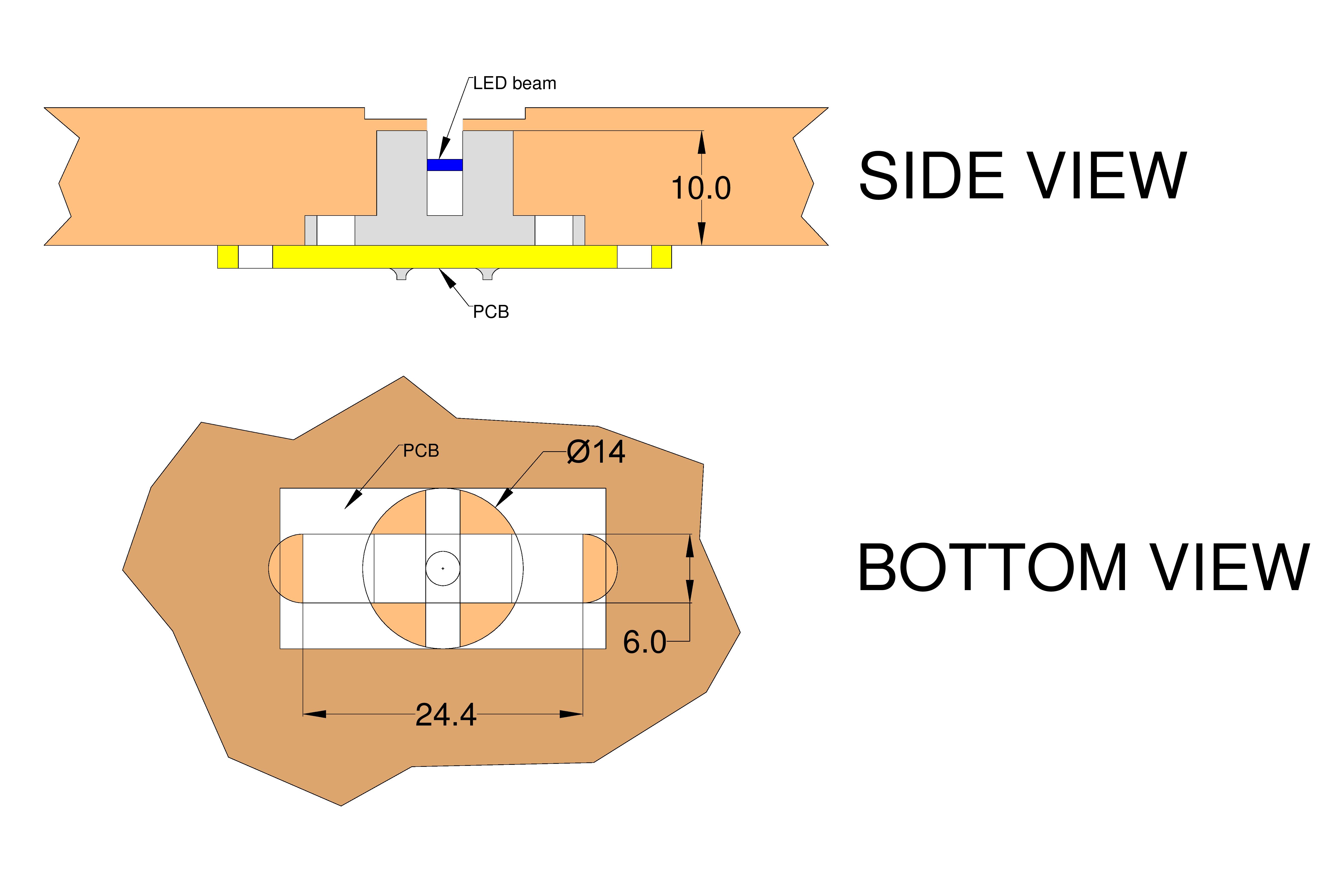
Figure 2: Slotted Optical Switches
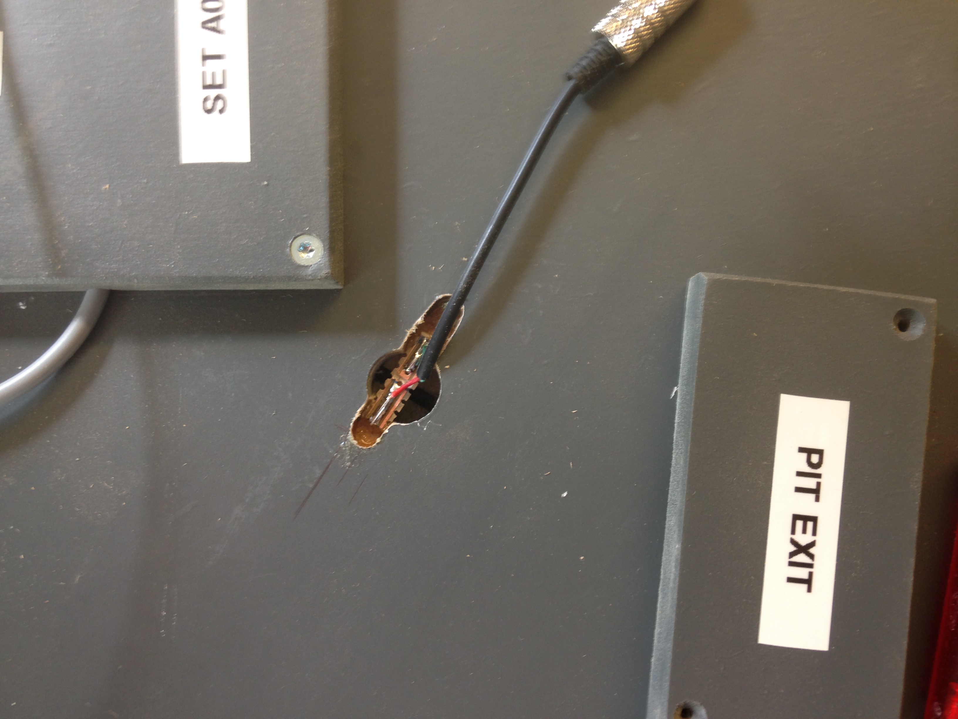
Pit speed limit sensors
I use SmartSensor to identify and reduce the speed of a car going through the pit. The set is delivered with either 1,5 or 5 m long sensor cables. The cables are connected to a Arduino board, which is connected to the computers USB port.
- Mark the location of the entry and exit sensor.
- Drill a 3 mm hole through the slot.
- From the back side, route with your braid router¹ a 10 mm deep hole.
Exactly the same way as for the SOS‘s. - I have secured the sensors with a few drops of glue.
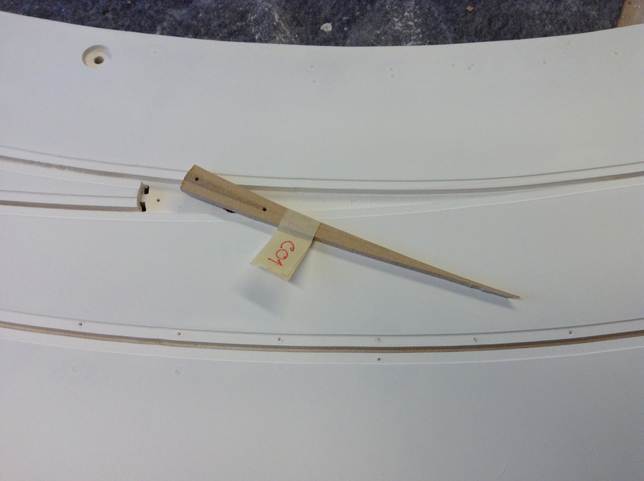
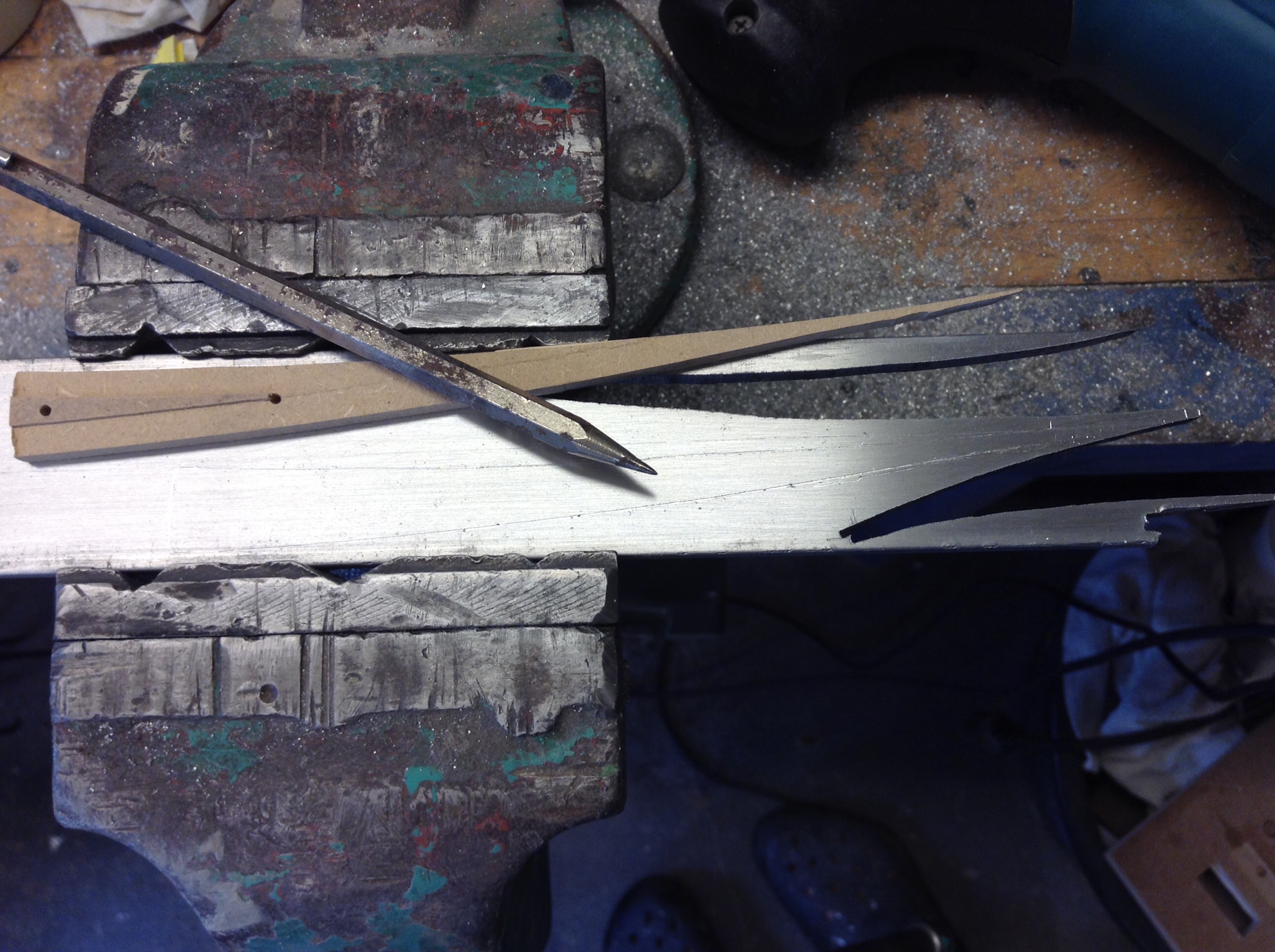
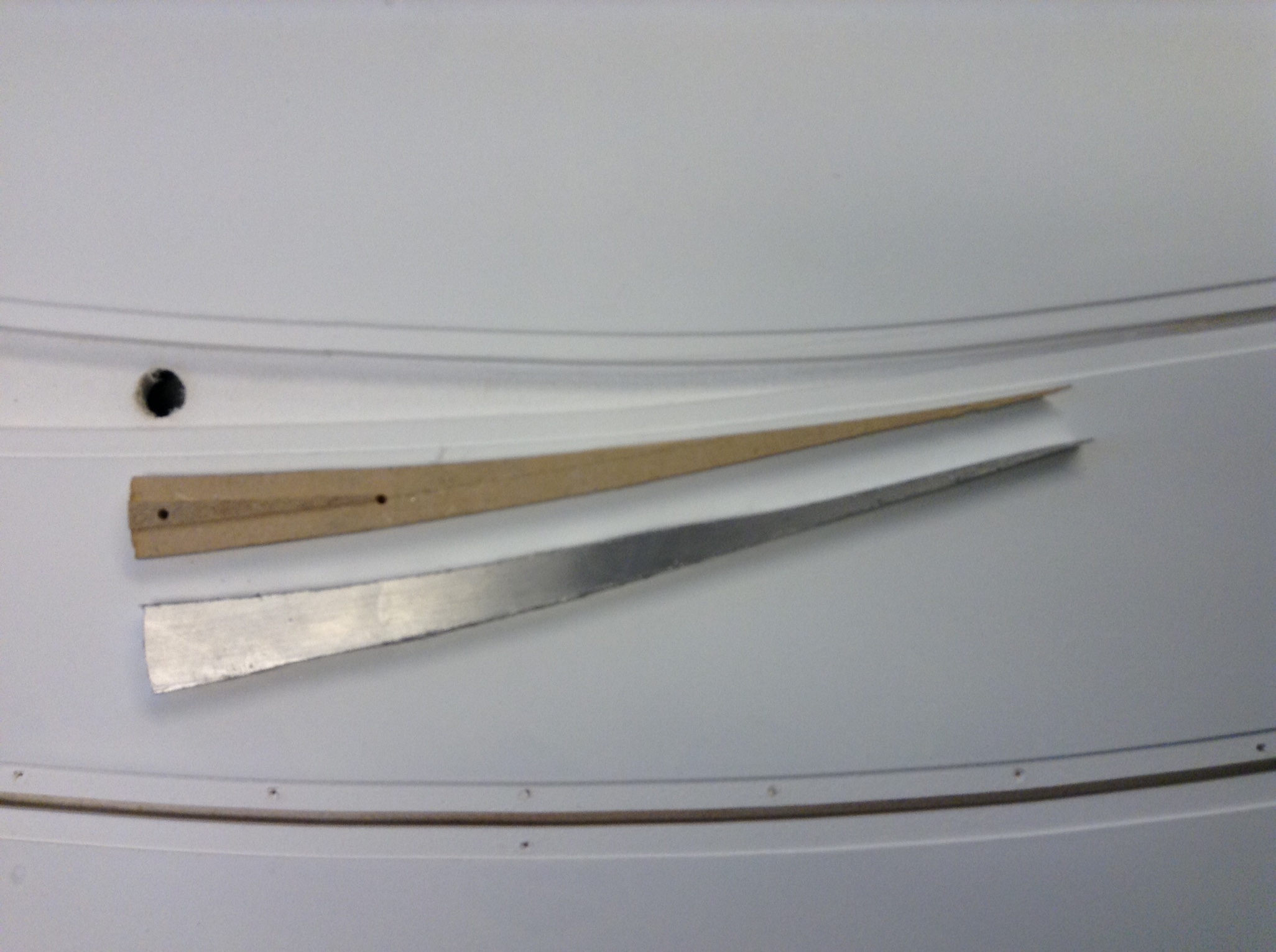
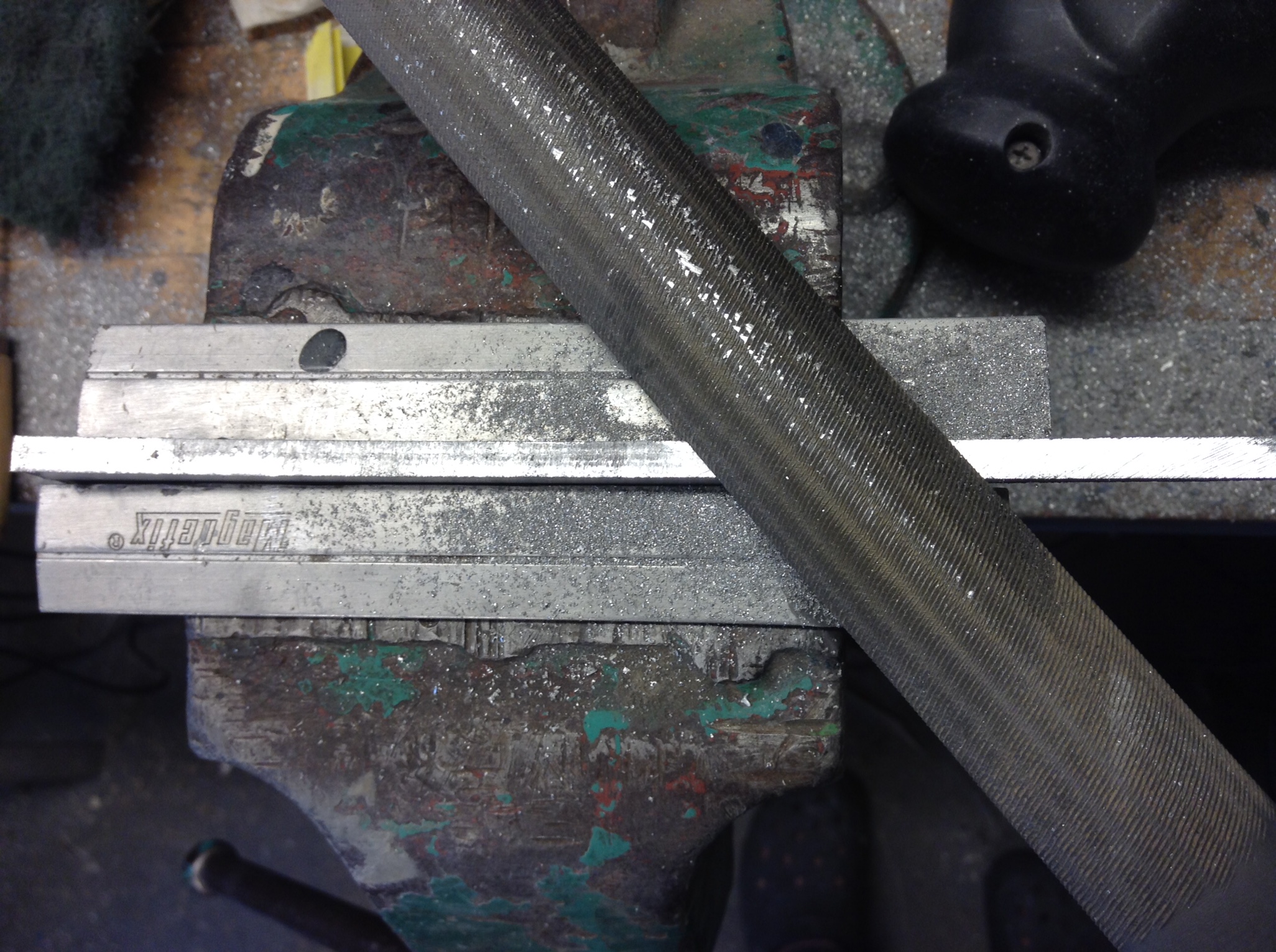
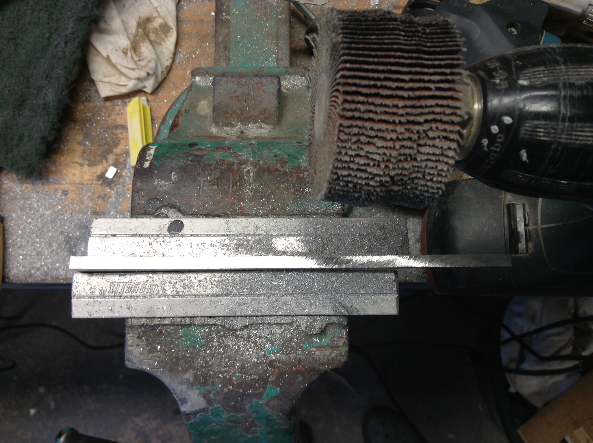
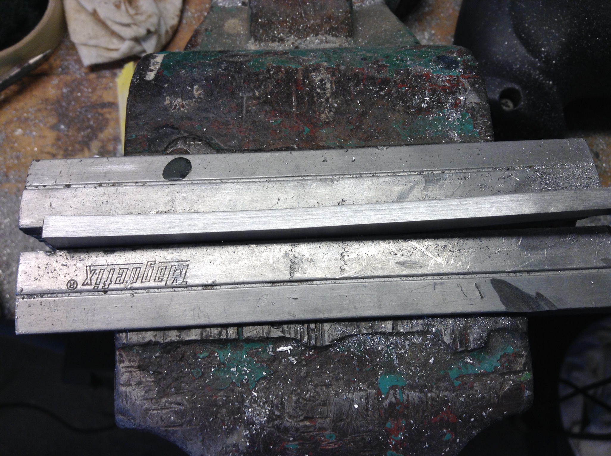
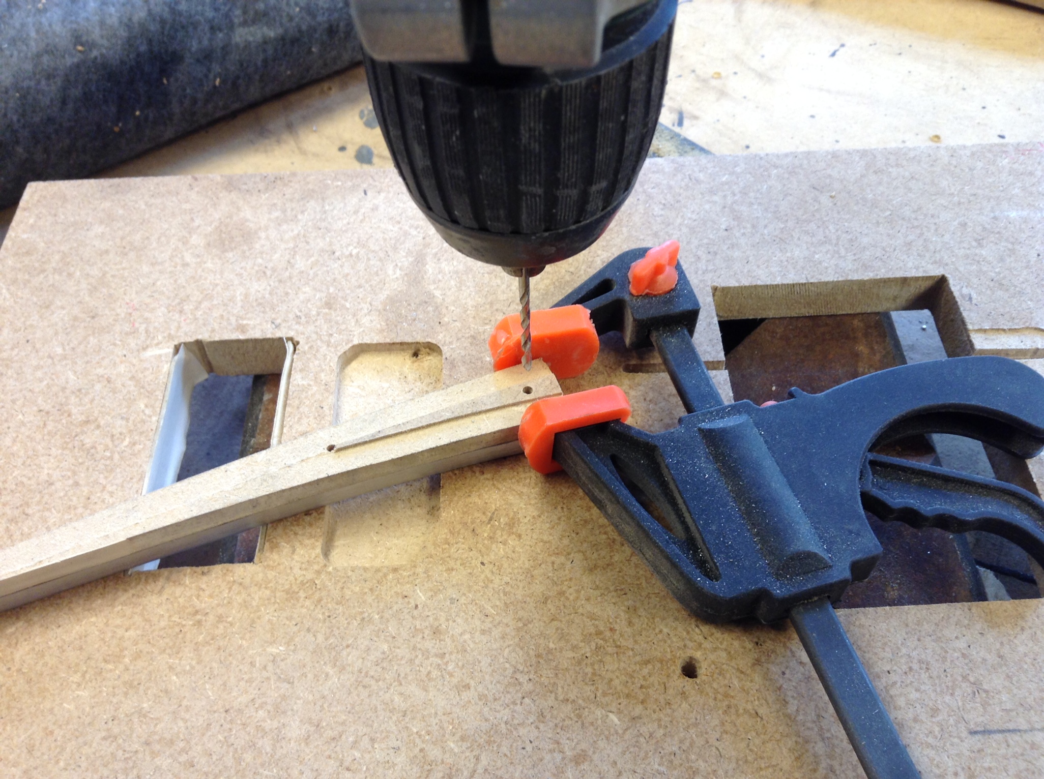
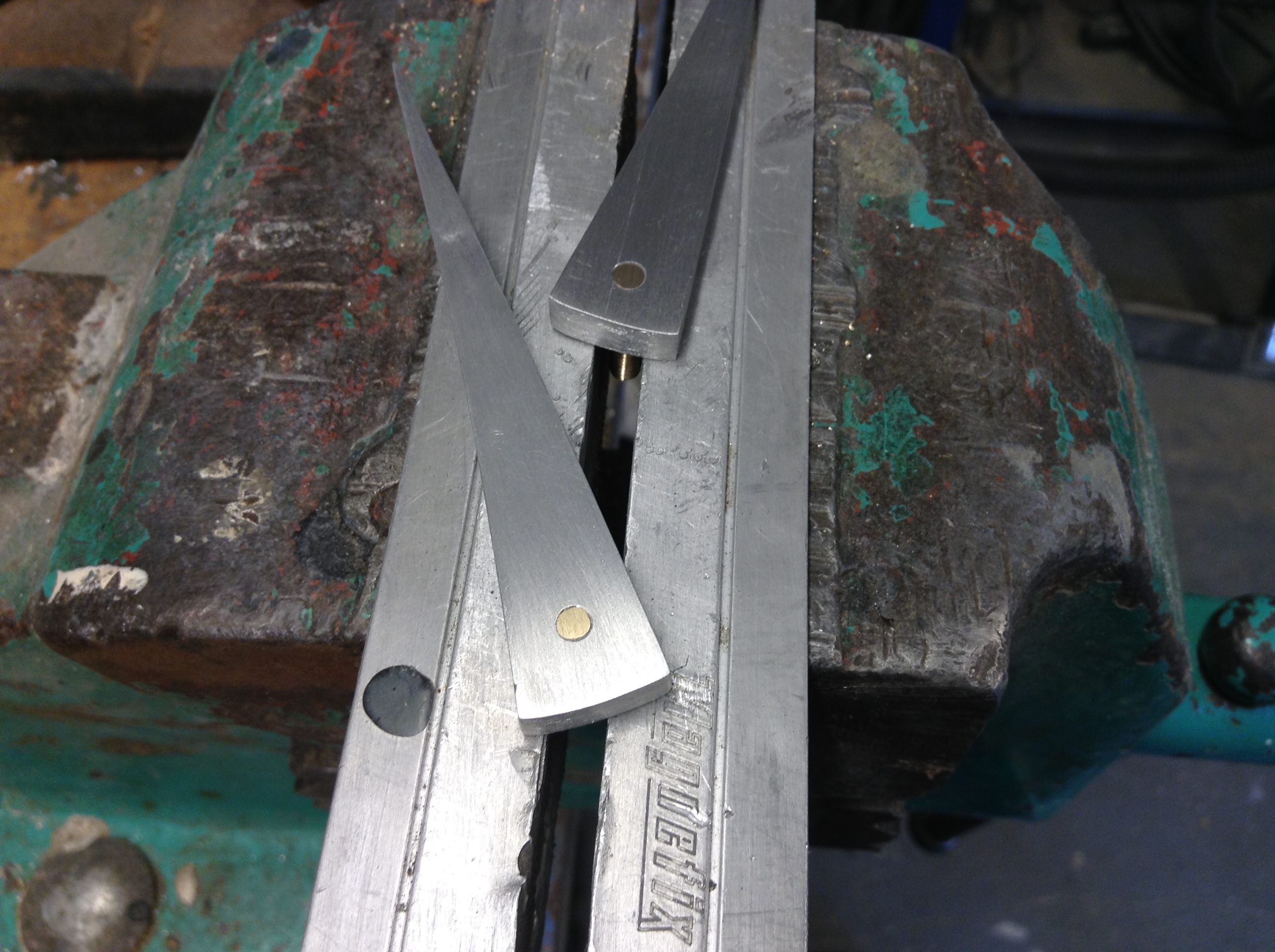
Aluminium flipper
- Use the copy of the “MDF flipper”¹, as a template for the 5 mm aluminium flipper. Cut and grind it to the right shape.
- Dill a 2 mm hole 4 mm deep for the solenoid connection pin.
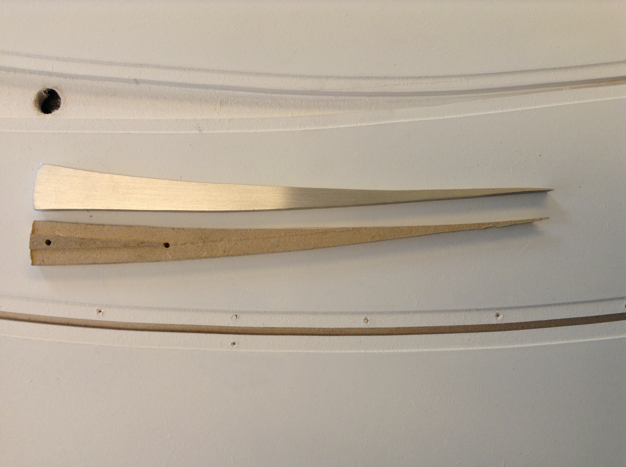
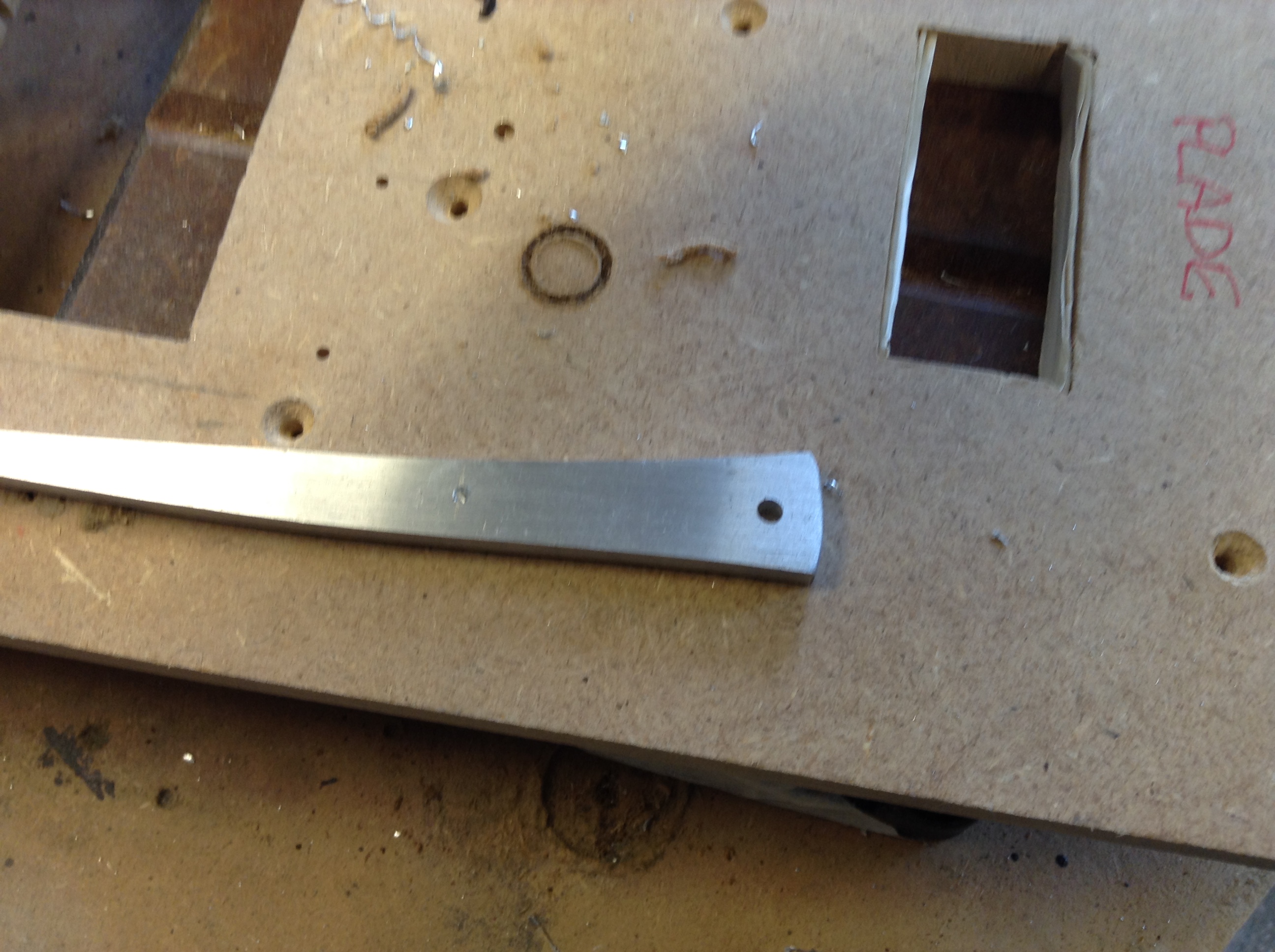
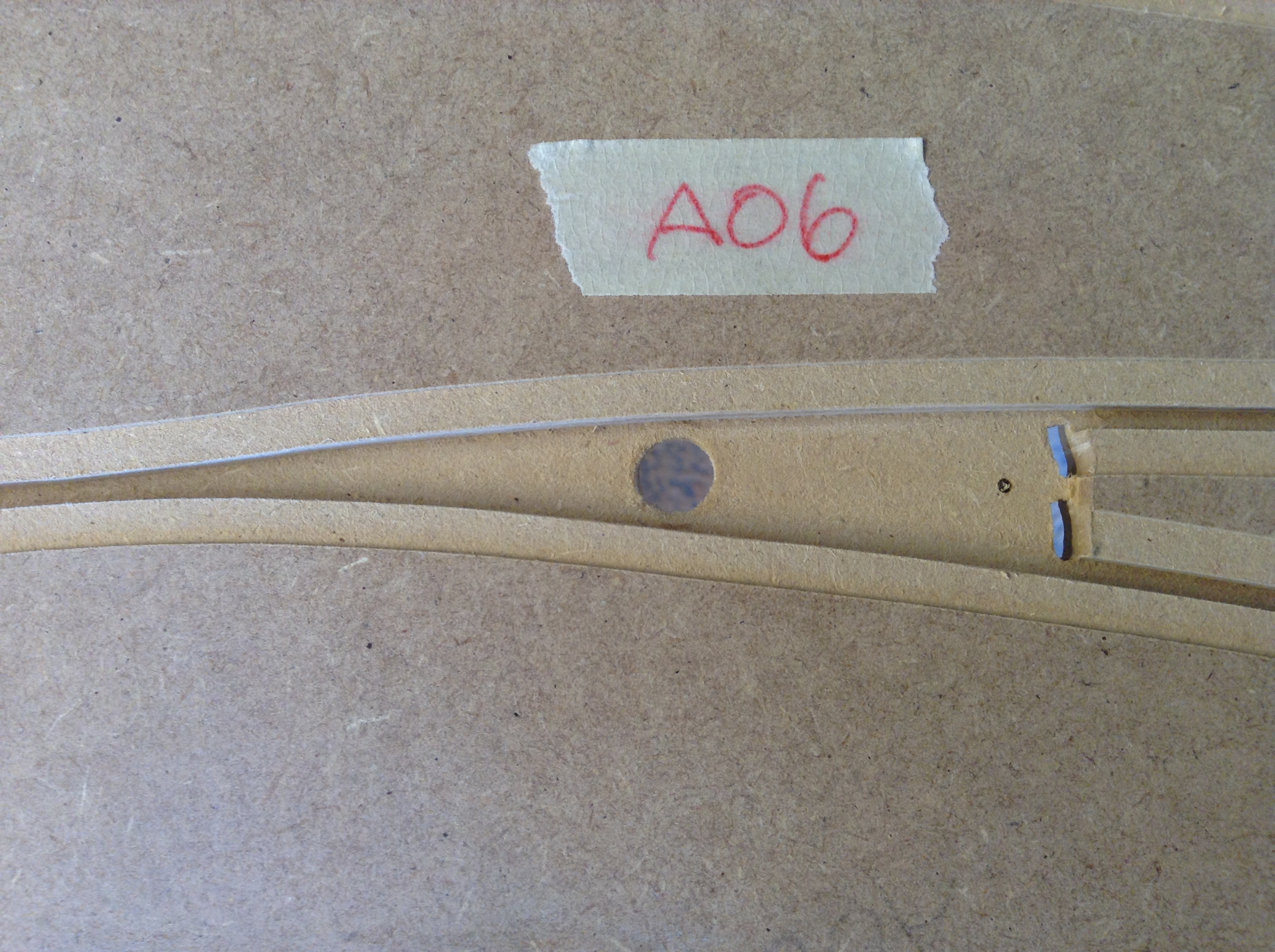
- The 3 types of flipper:
- Anti Collision LC: Glue a 15 mm long 2 mm wire in to the hole. I use a Loctite XXXXXXXX.
- Scalextric LC: Just leave the 2 mm hole, it will later fit the original Scalextric plastic solenoid connection pin.
- Passive OUT flipper: Drill it up to 2,5 mm right through the flipper and cut a M3 thread.
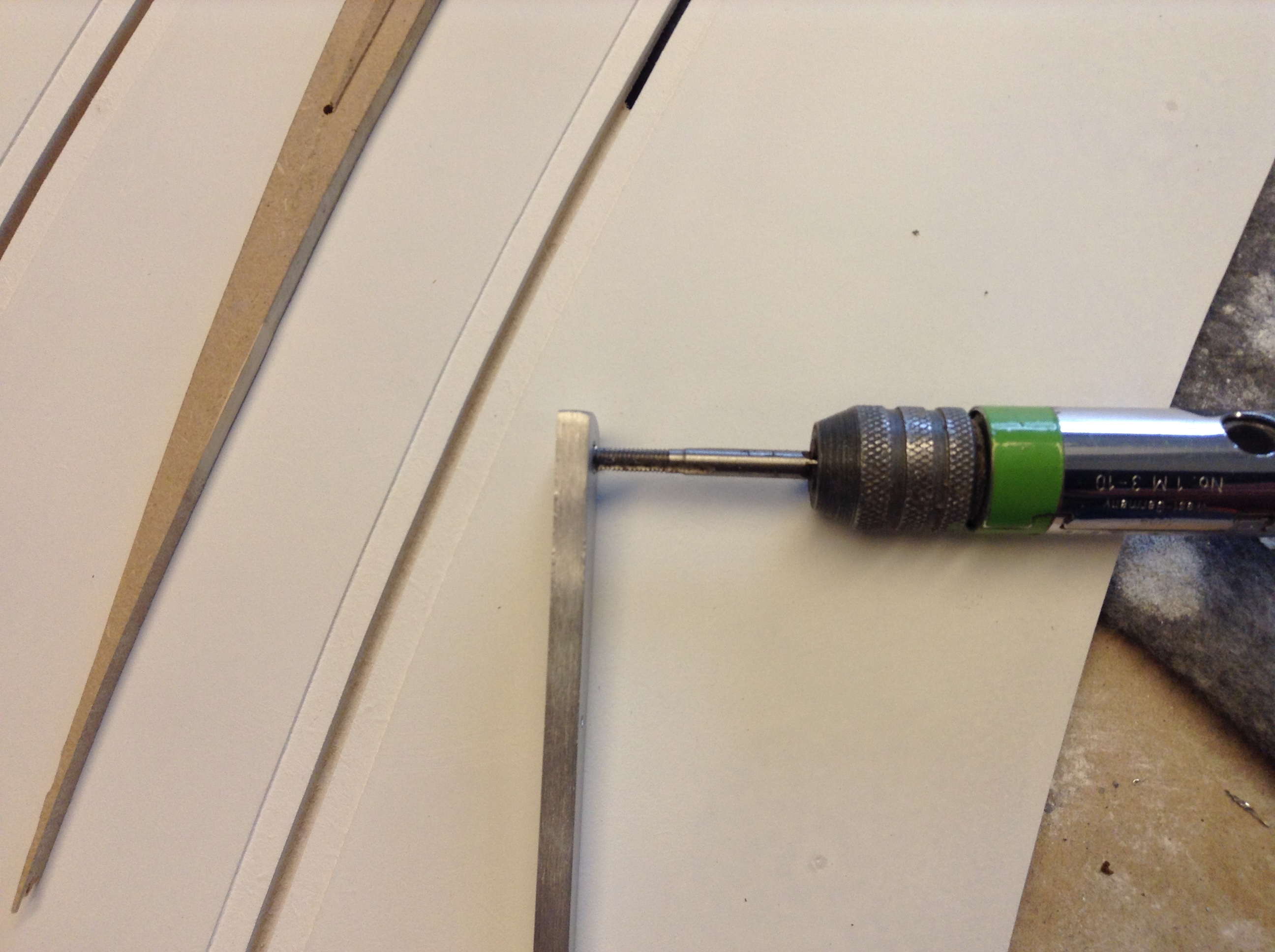
- Drill a 3,3 mm hole in all the active flippers for the axle right through it and cut a M4 thread.
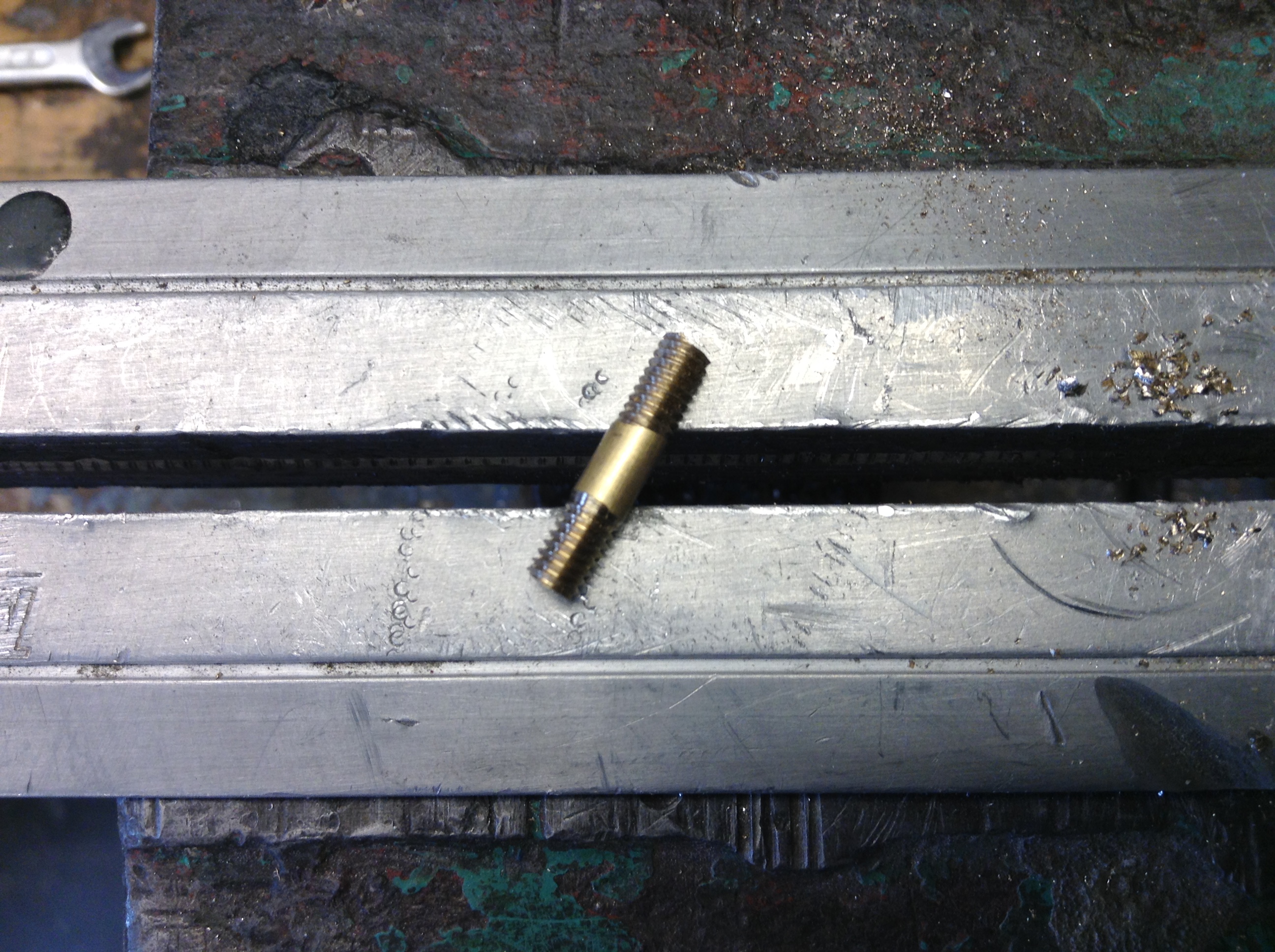
- I make the axle out of Ø 4 mm brass 17 mm long with home cut tread in both ends.
- Screw the axle in the flipper and secured it with a drop of Loctite tread lock.
- Grind the tip of the axle until it fit flush with the surface.
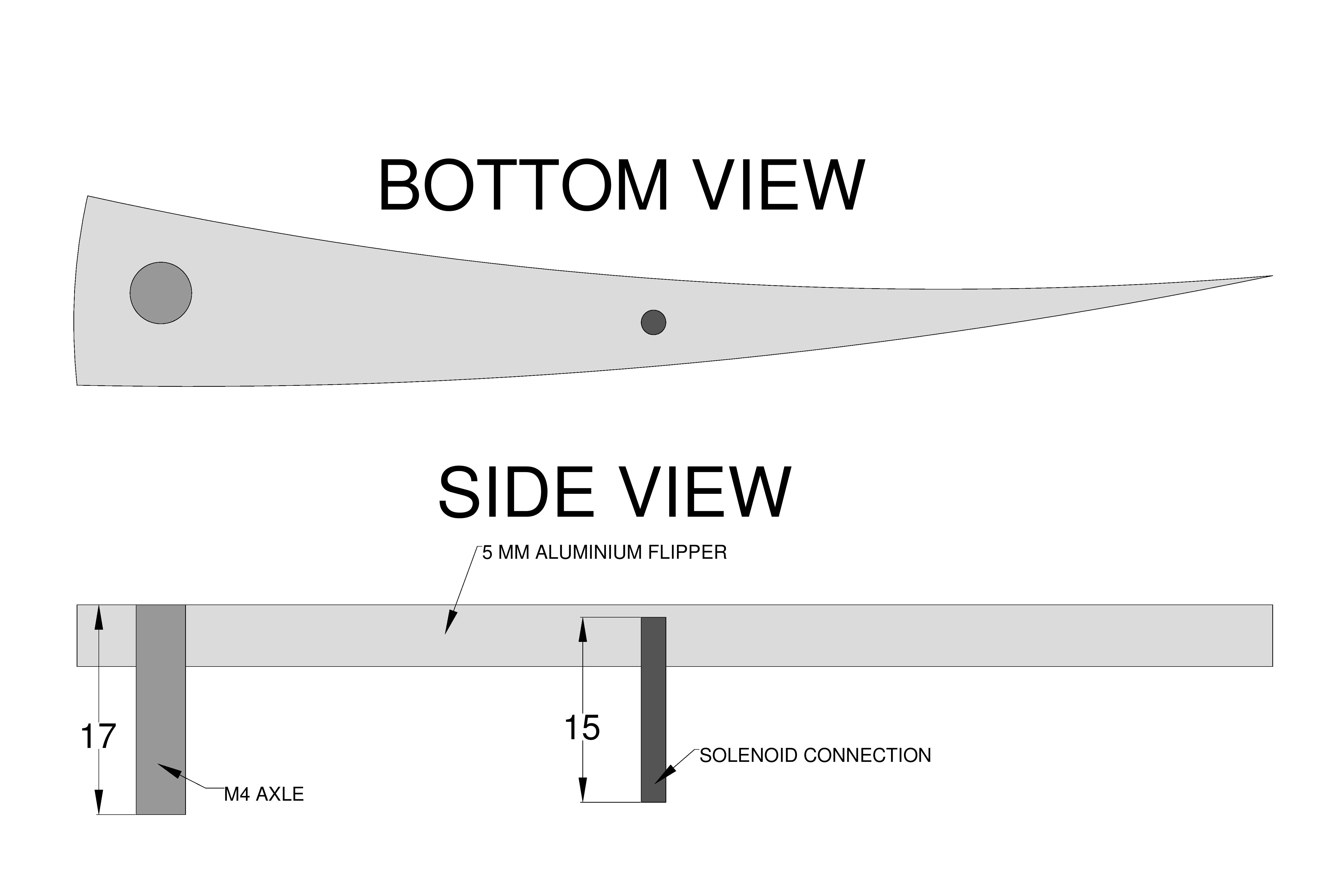
Figure 3: LC flipper
Flipper bearing
- From the front side increase the 2 mm temporary hole¹ up to 5,5 mm.
- Increase the axle hole to 6 mm but drill backwards! If you drill forwards the hole will be a tiny bit to big.
- Now press a 6 mm thick aluminium tube, 6 mm long, into the hole so it fit flush in both ends.
The aluminium tube is 4 mm inside and it fits perfect as bearing for the 4 mm brass axle. - The distance between the flipper and the surface of the MDF is adjusted with a thin flat washer.
- After paint the axle will be secured with a nylon insert lock nut with a eye terminal used as flat washer underneath. The “live” wire from the PCB is connected to that eye terminal.
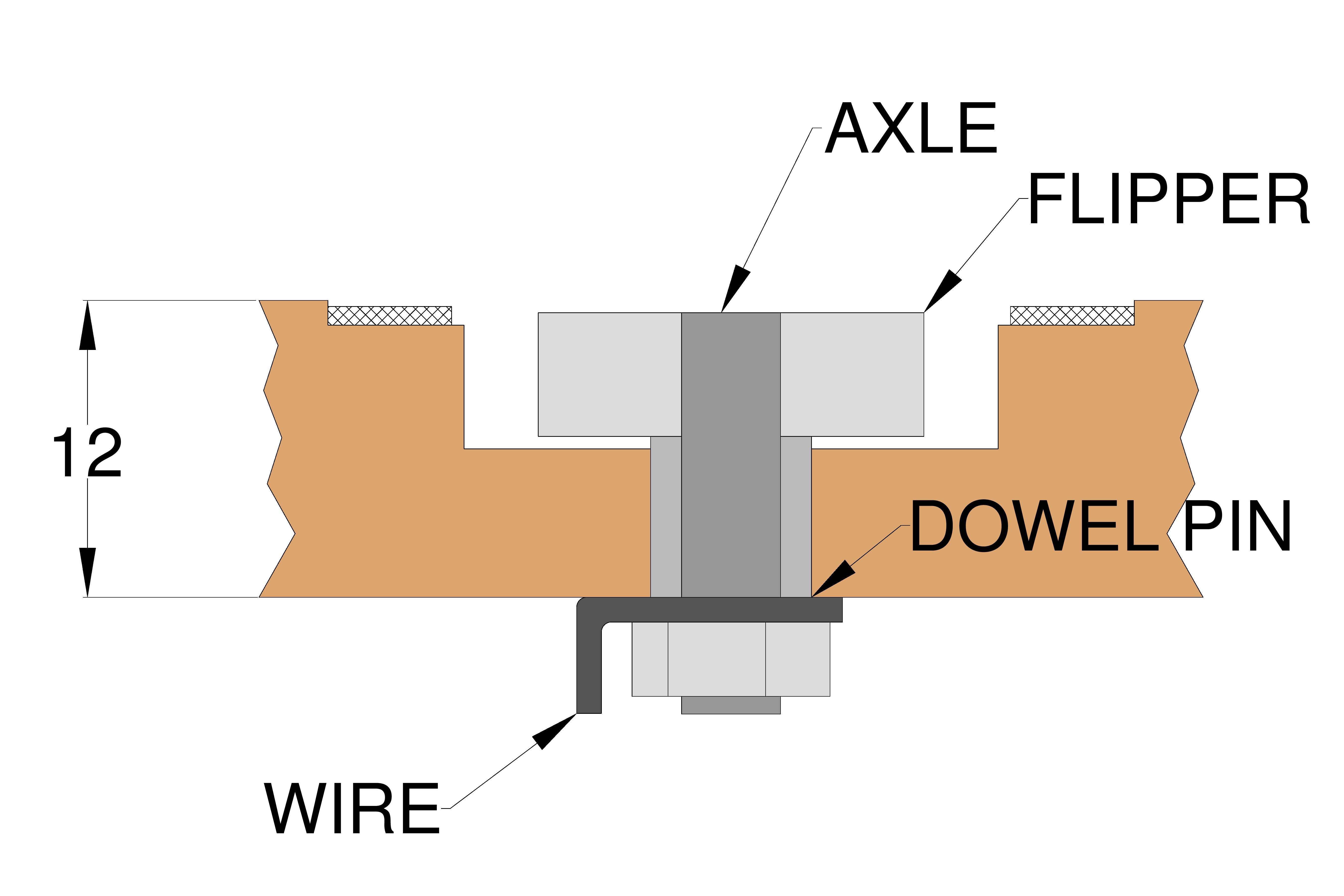
Figure 4: Axle
Anti Collision LC
Most of the work with this system is already done – the optical switches, axle and the flippers, the only thing missing is the solenoid and the electronics.
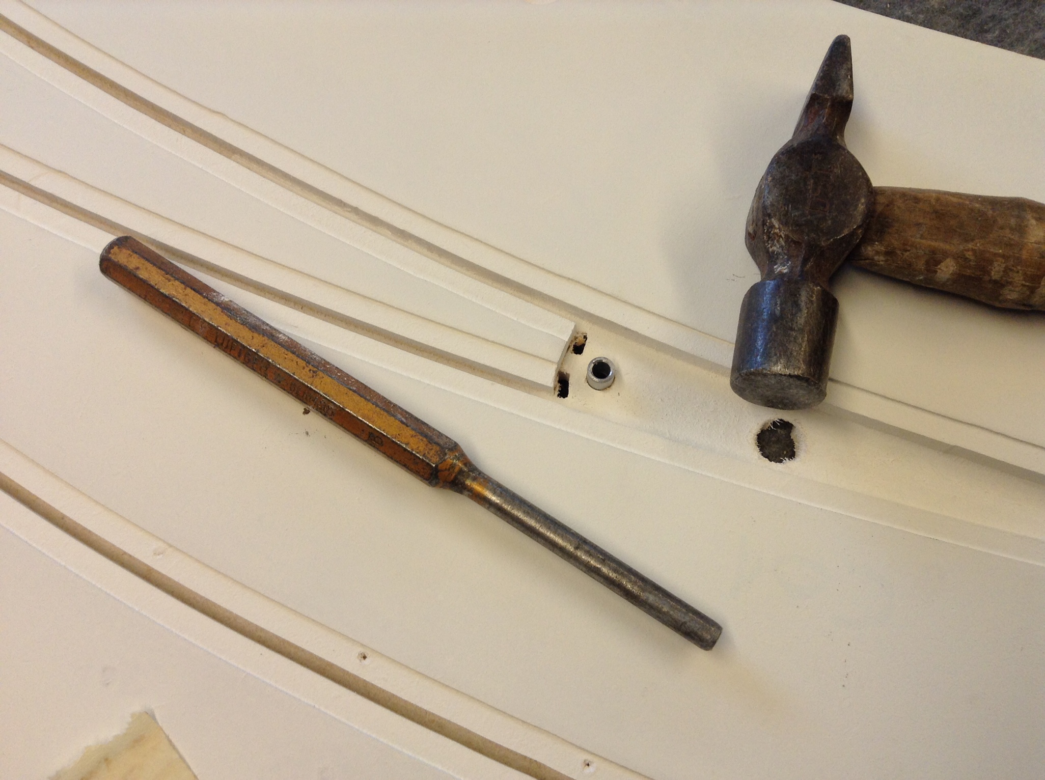
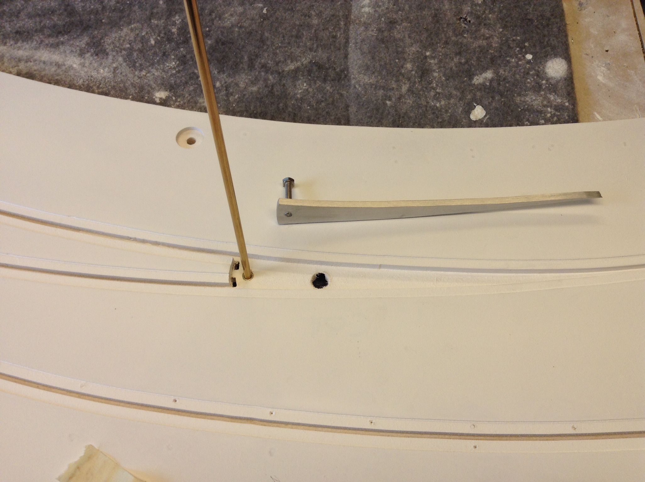
- Drill the temporary solenoid connections point hole¹ up from 2 to 10 mm in small steps.
- Route space for the solenoid and its axle. I use a home made router base for that purpose.
See the measurements on figur 5. - Route space for the PCB. I don’t use a template, I do it by free hand.
- After paint and wirering there will be mounted MDF cover for protection.
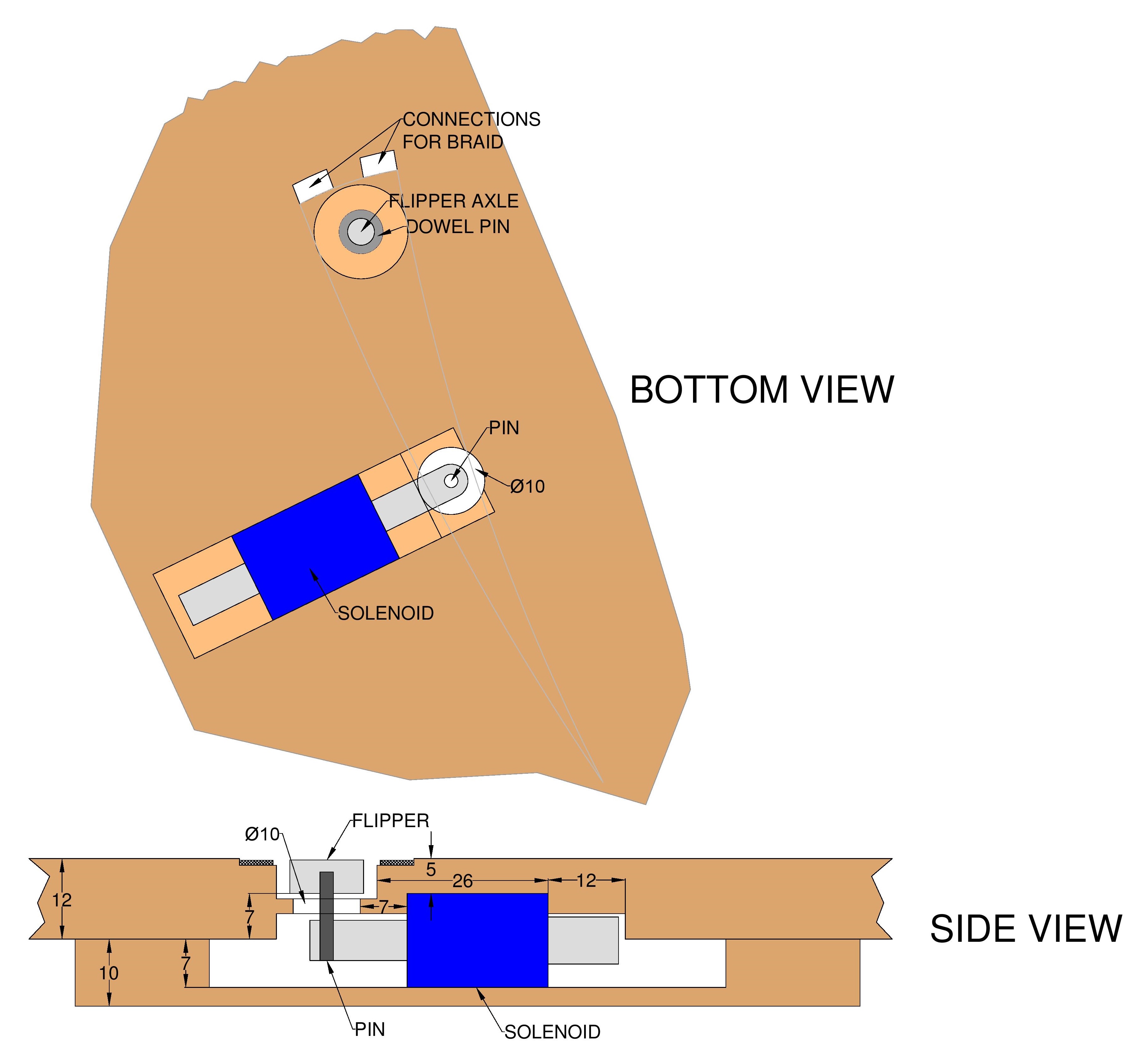
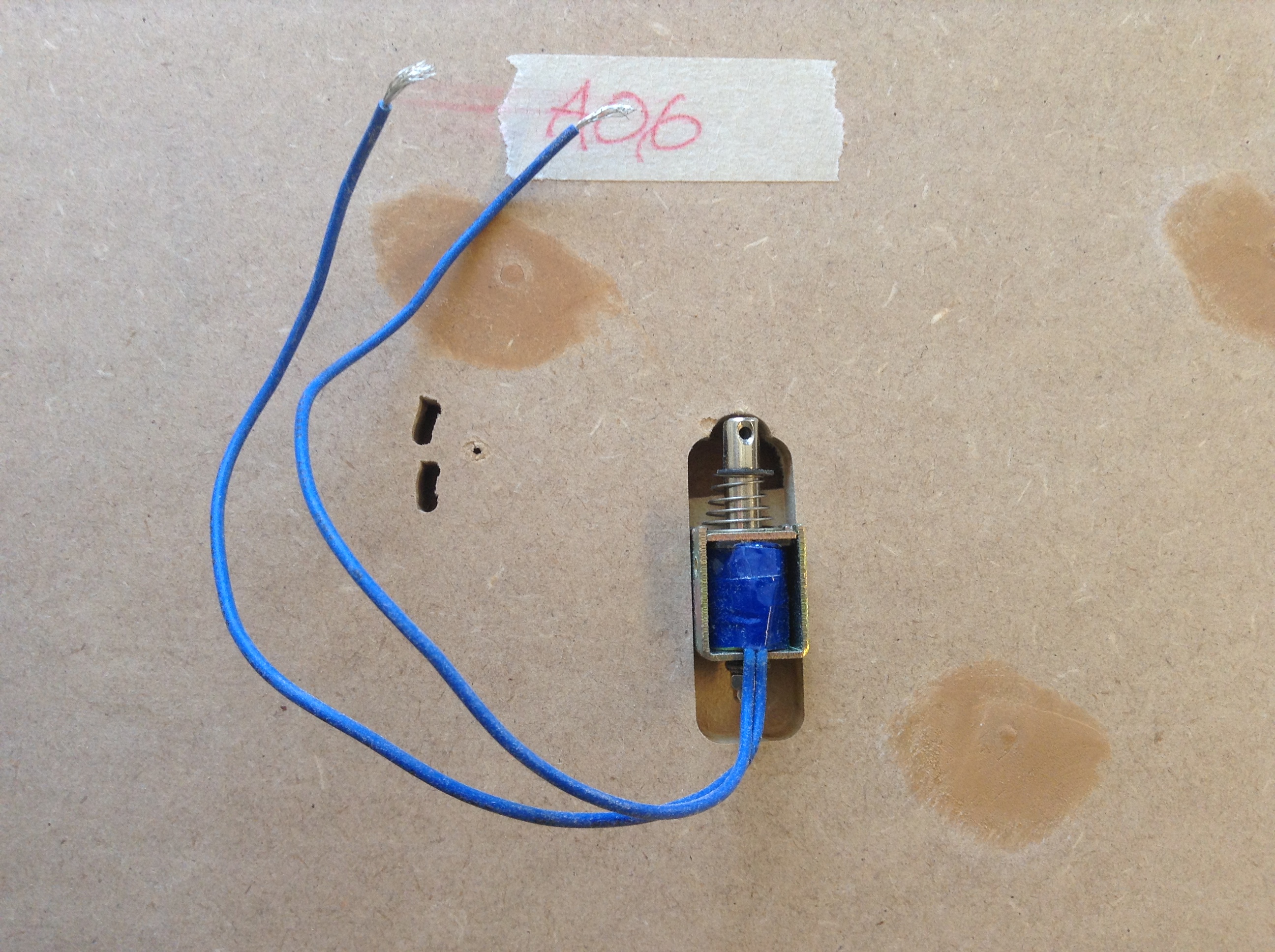
Figure 5: Solenoid Connection
Scalextric LC
- Make the flippe the exactly same way as described for the Anti Collision LC.
- At the solenoid connection point route a 70 x 6 x 6 mm slot for the two Scalextric solenoids. Because the solenoids is nearly 1 mm thicker at the end, where the wires are connected, I have to increase the slot a bit.
See the measurements on figur 6. - Mark the location for the Scalextric LED PCB. On a Scalextric plastic rail it’s located 185 mm before the tip of the flipper and that’s what I will do.
- Drill a 3 mm hole through the slot to identify the location.
- Route space for the LED PCB.
See the measurements on figur 7. - Route space for the small relay PCB between the LED PCB and the solenoids.
- After paint and wirering there will be mounted MDF cover for protection.
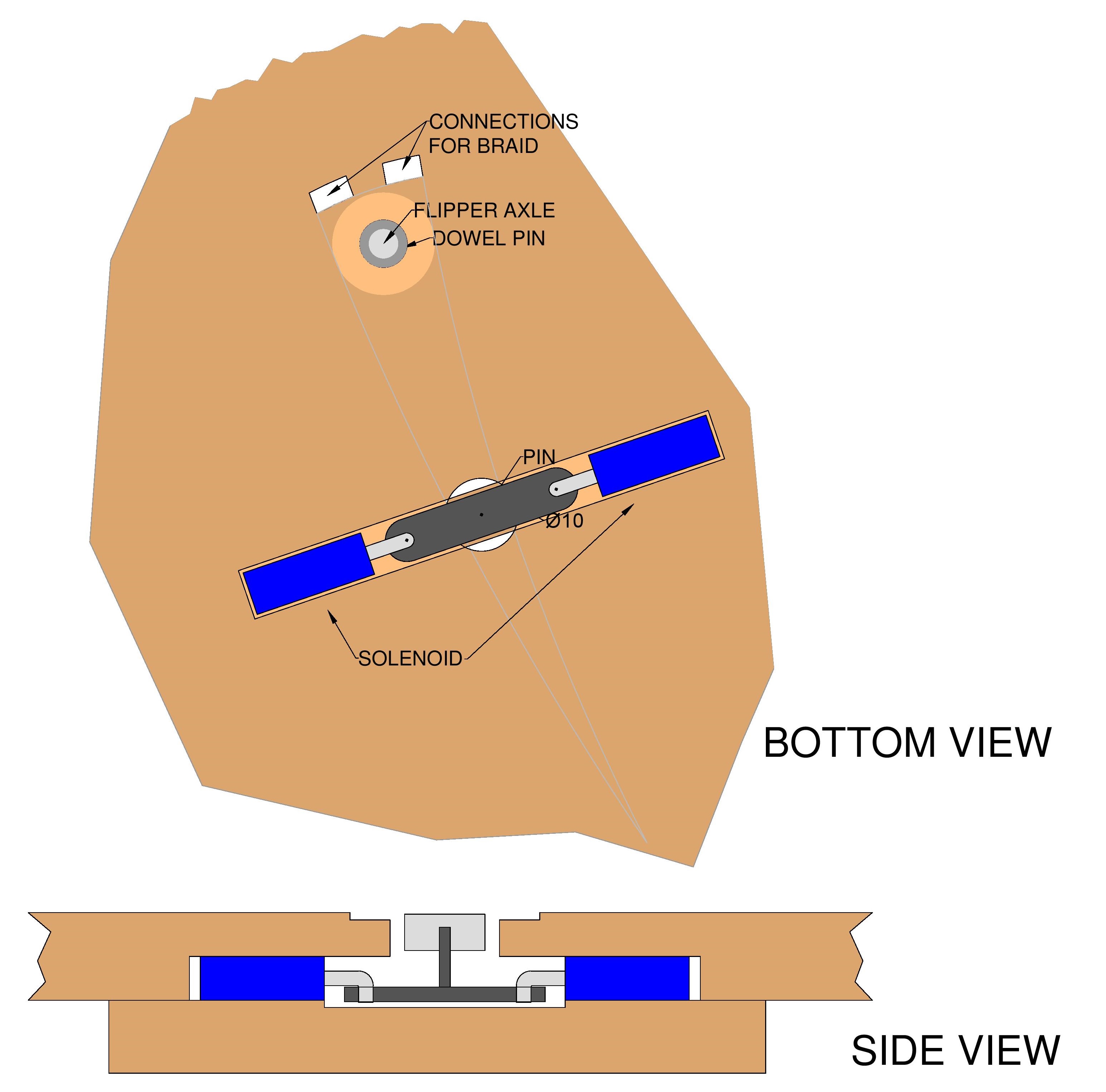
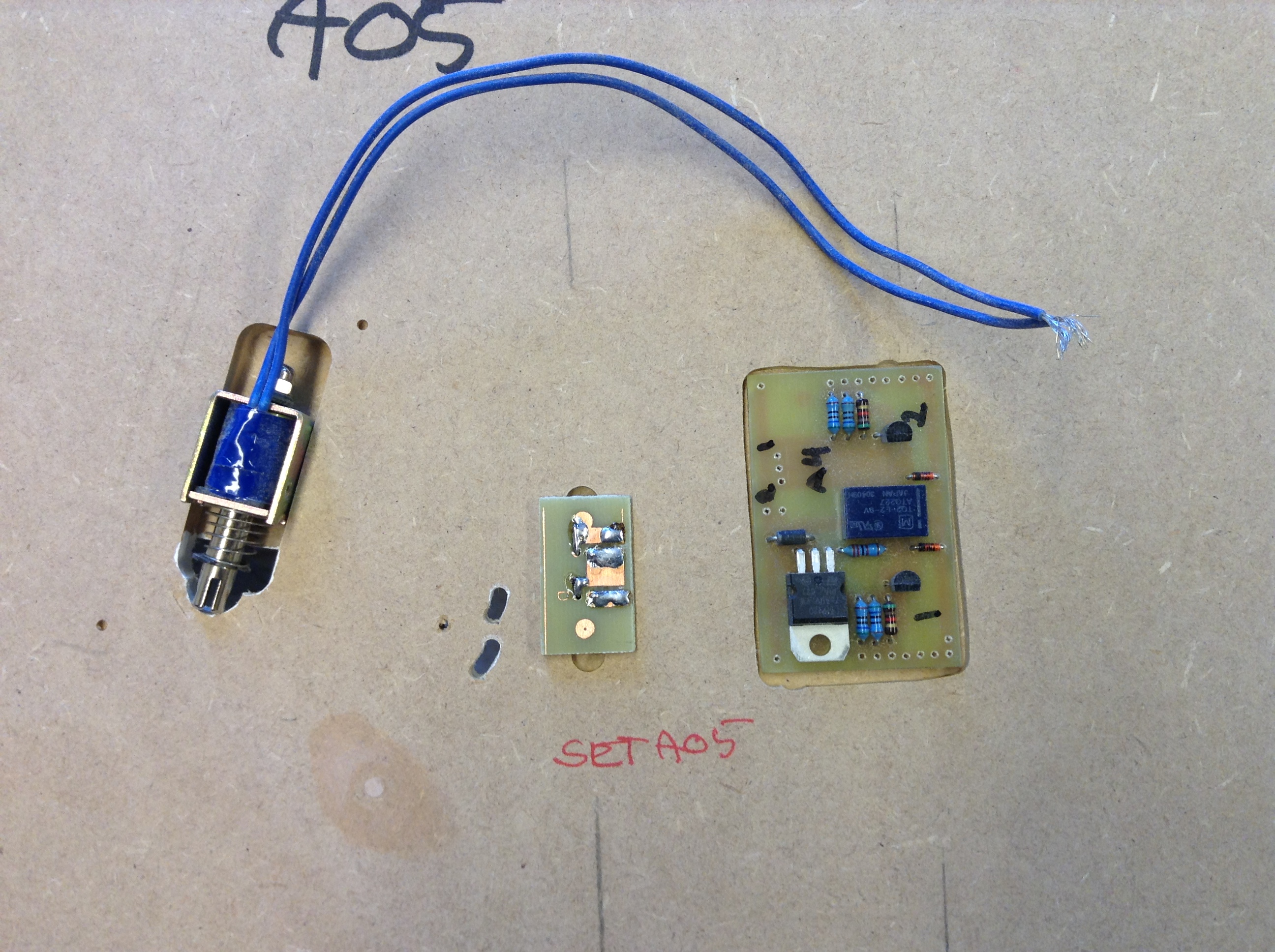
Figure 6: Scalextric solenoid connection.
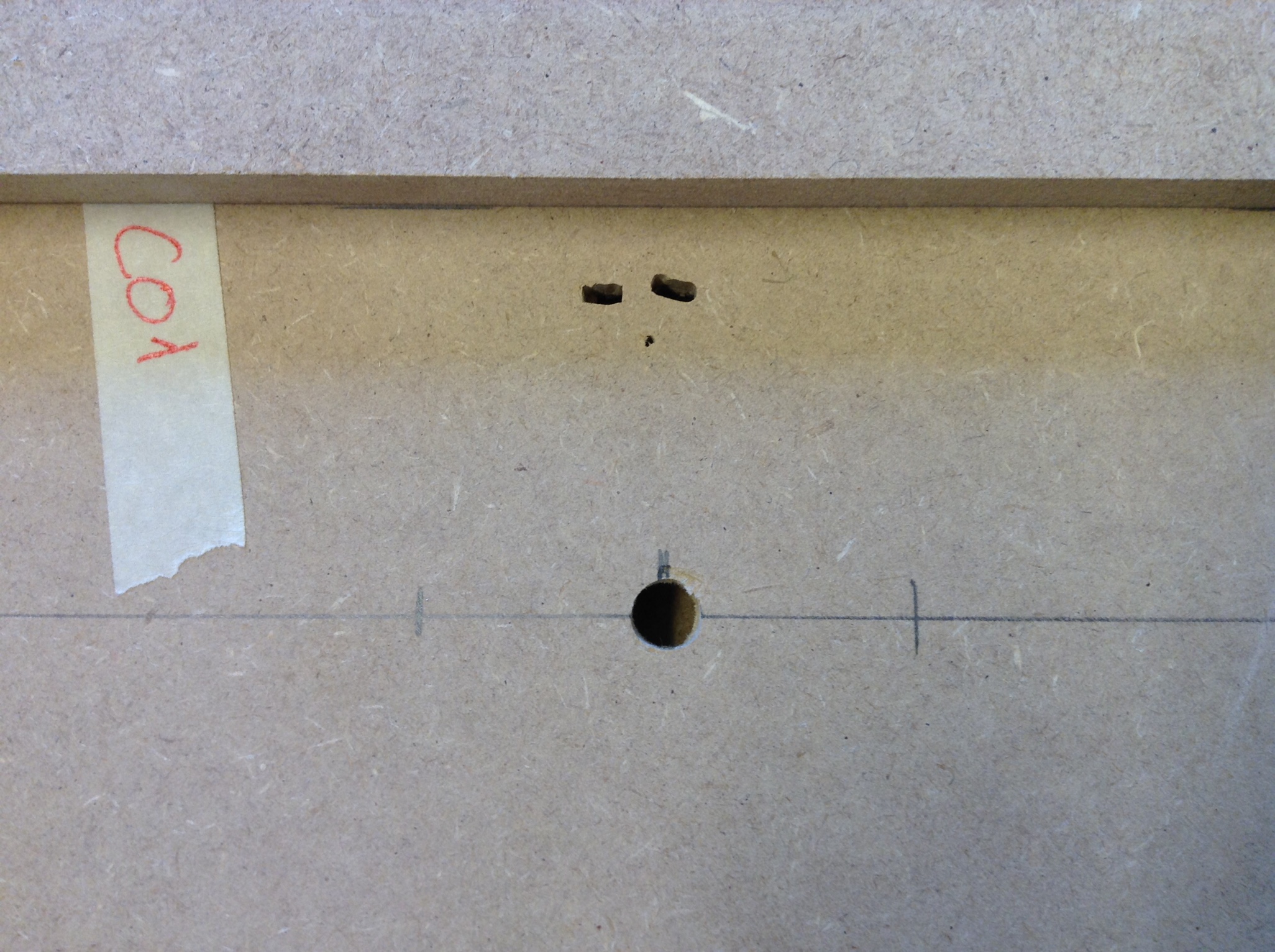
Figure 7: Scalextric LC PCB
Passiv OUT flipper
- Make the flippe the exactly same way as described for the Anti Collision LC
- Increase the 2 mm temporary hole¹ in the MDF to 5 mm. (The screw is only 3 mm but it’s nice to have the opportunity to adjust a little bit.)
- Route space for the 2 SOS‘s just before the flipper as described earlier.
- Route space for the PCB.
- When all the MDF is painted, glue and screw the flipper to the MDF and connect it to the PCB.