Scalextric LC
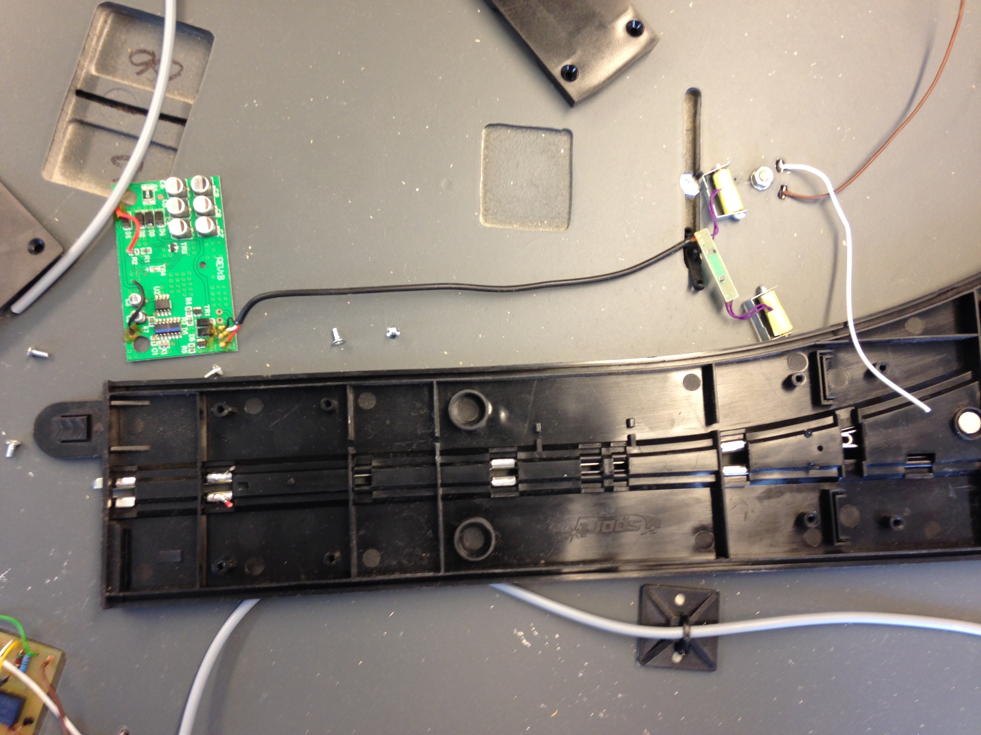
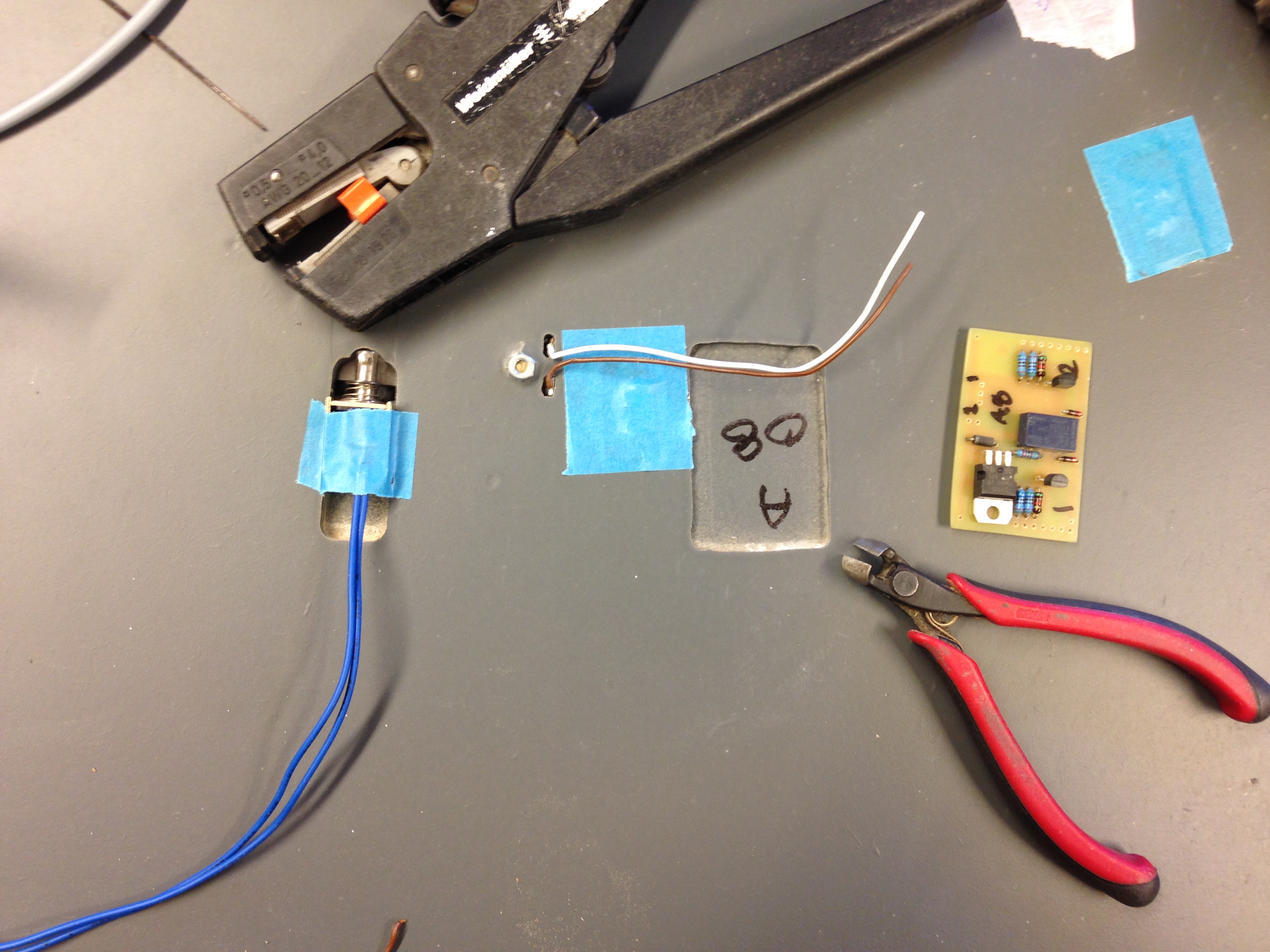
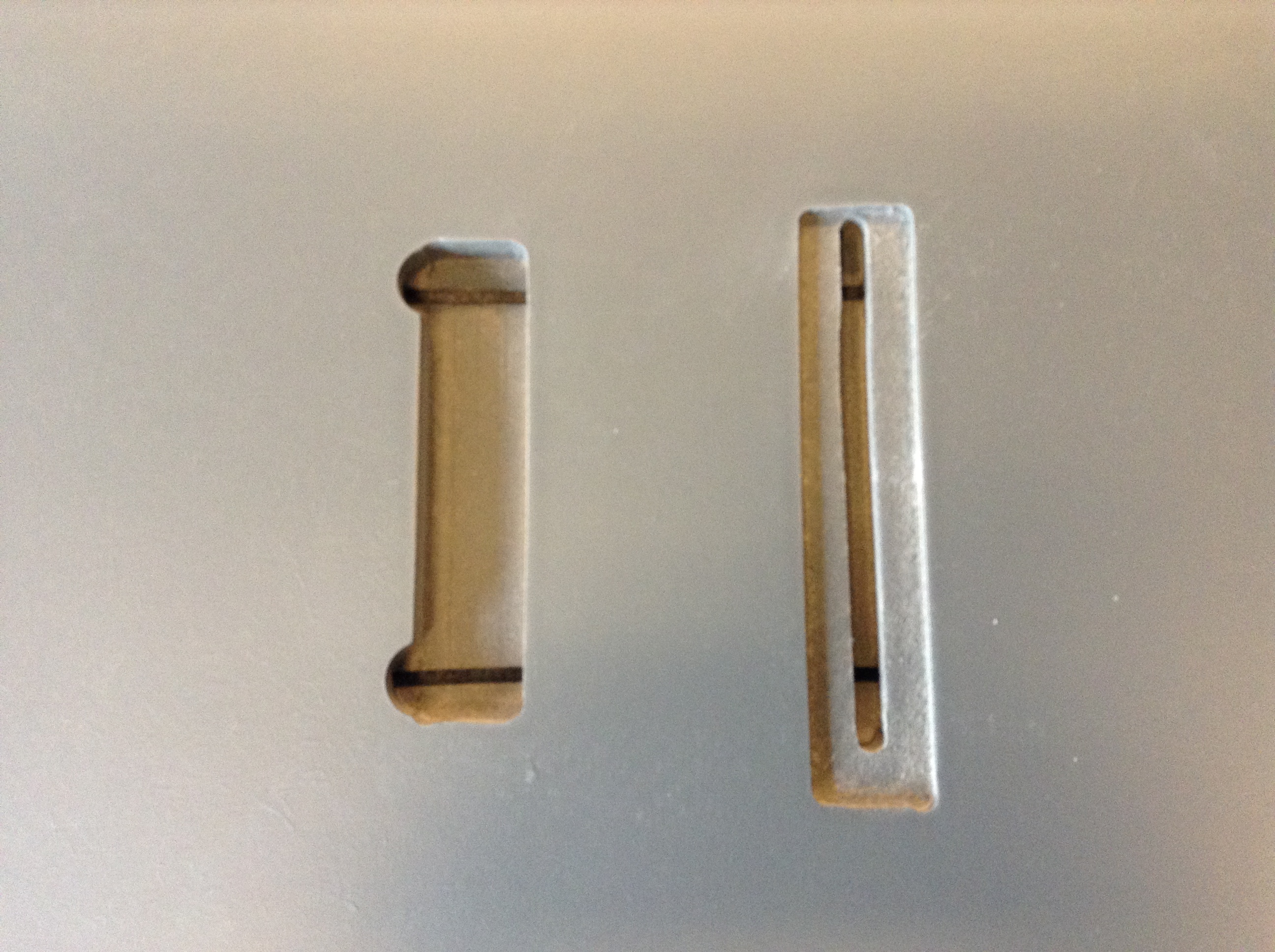
I have stripped some Scalextric C7014/15 pit LC‘s for LED PCB and solenoids. The solenoids and the plastic connection pin, have to be adjusted, so that the flipper will move freely. I test the movement with a PSU connected directly to the solenoids.
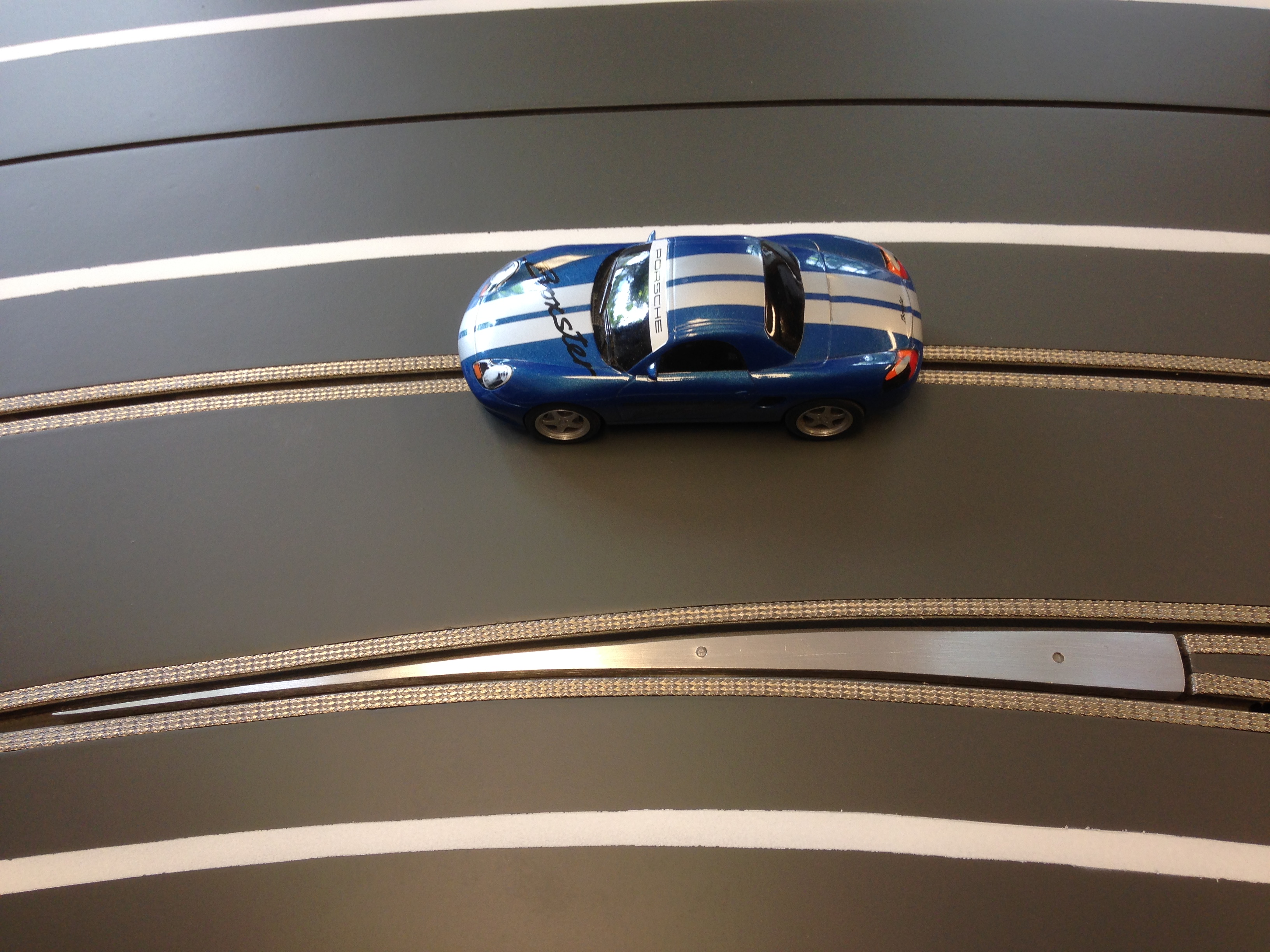
Clip 1: Testing built-in Scalextric LC with my ugly Porsche Boxster:)
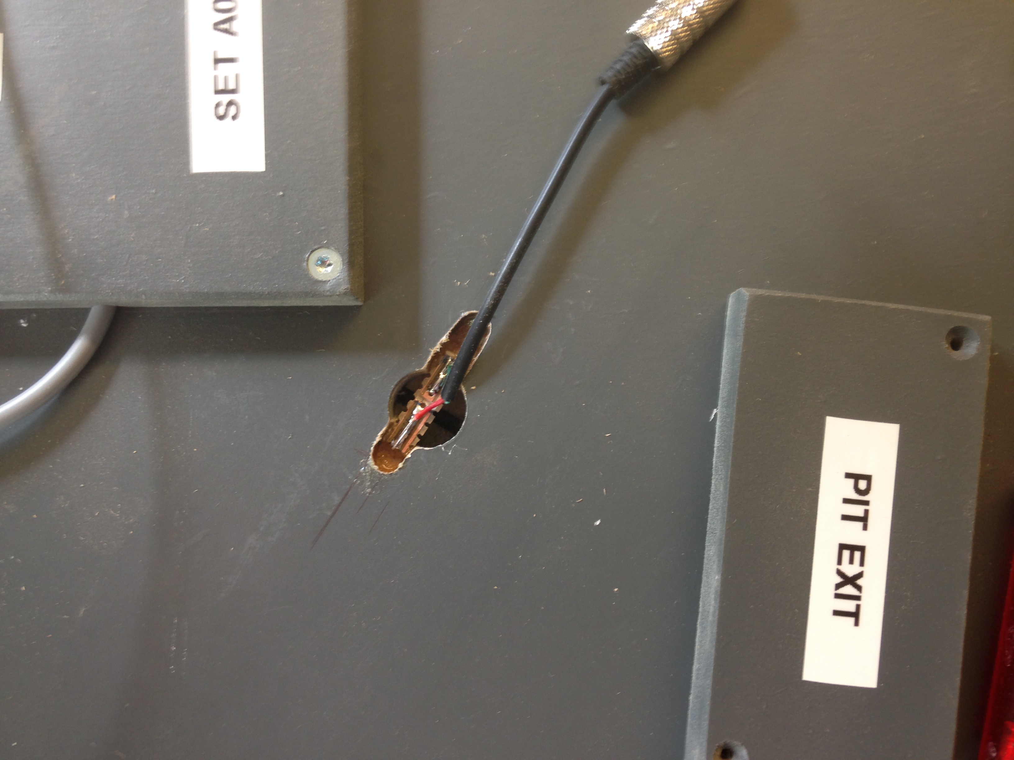
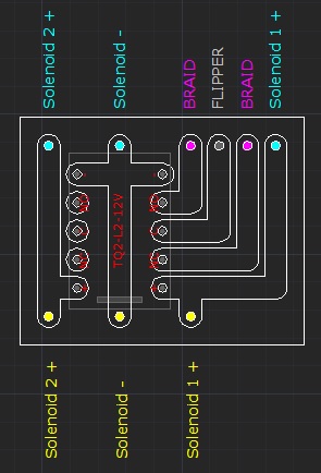
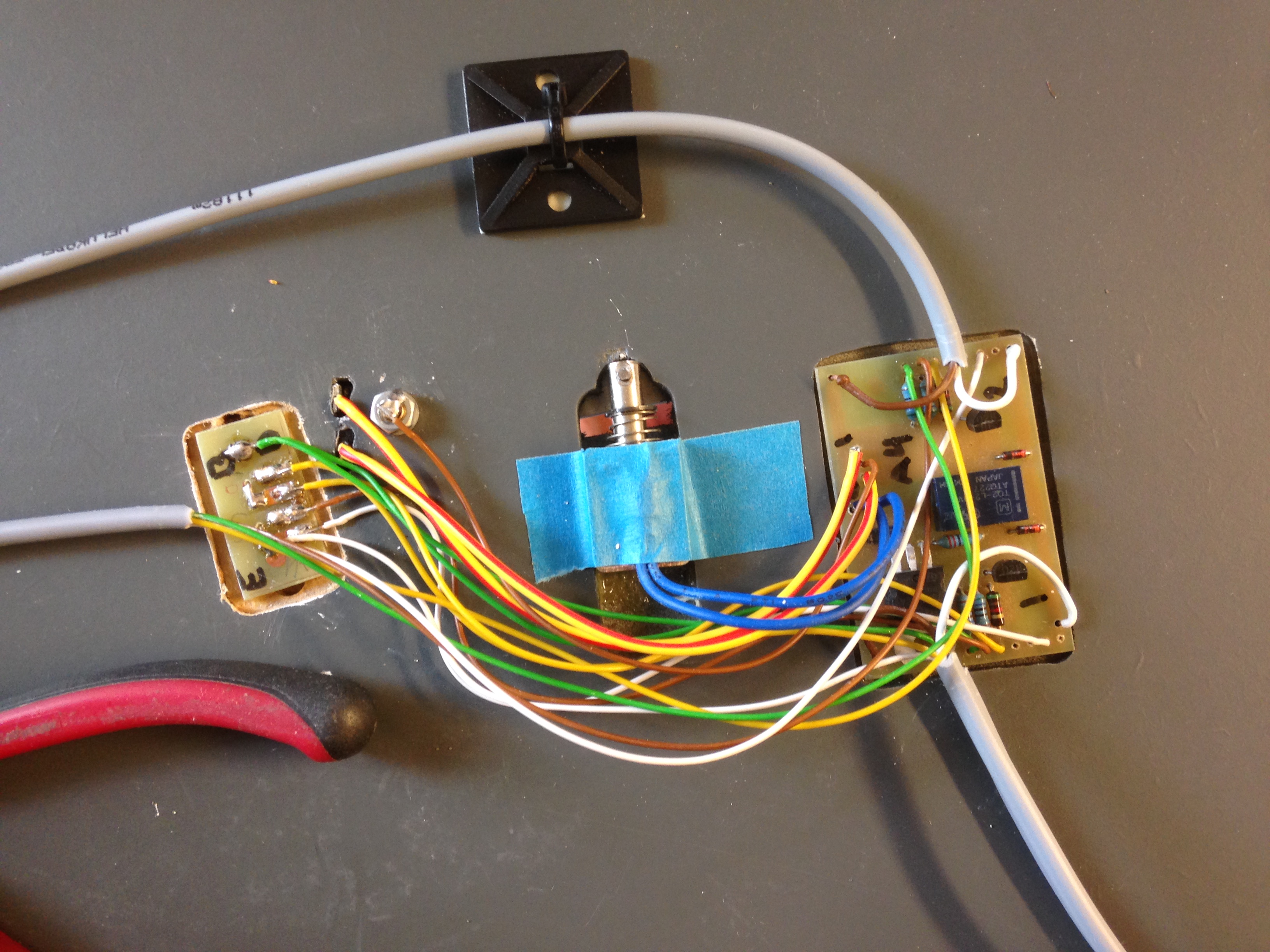
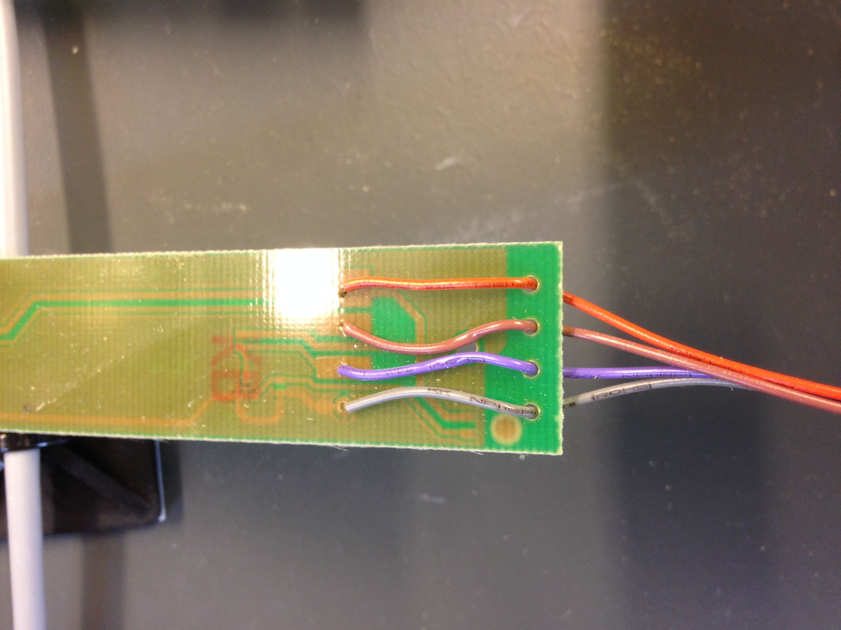
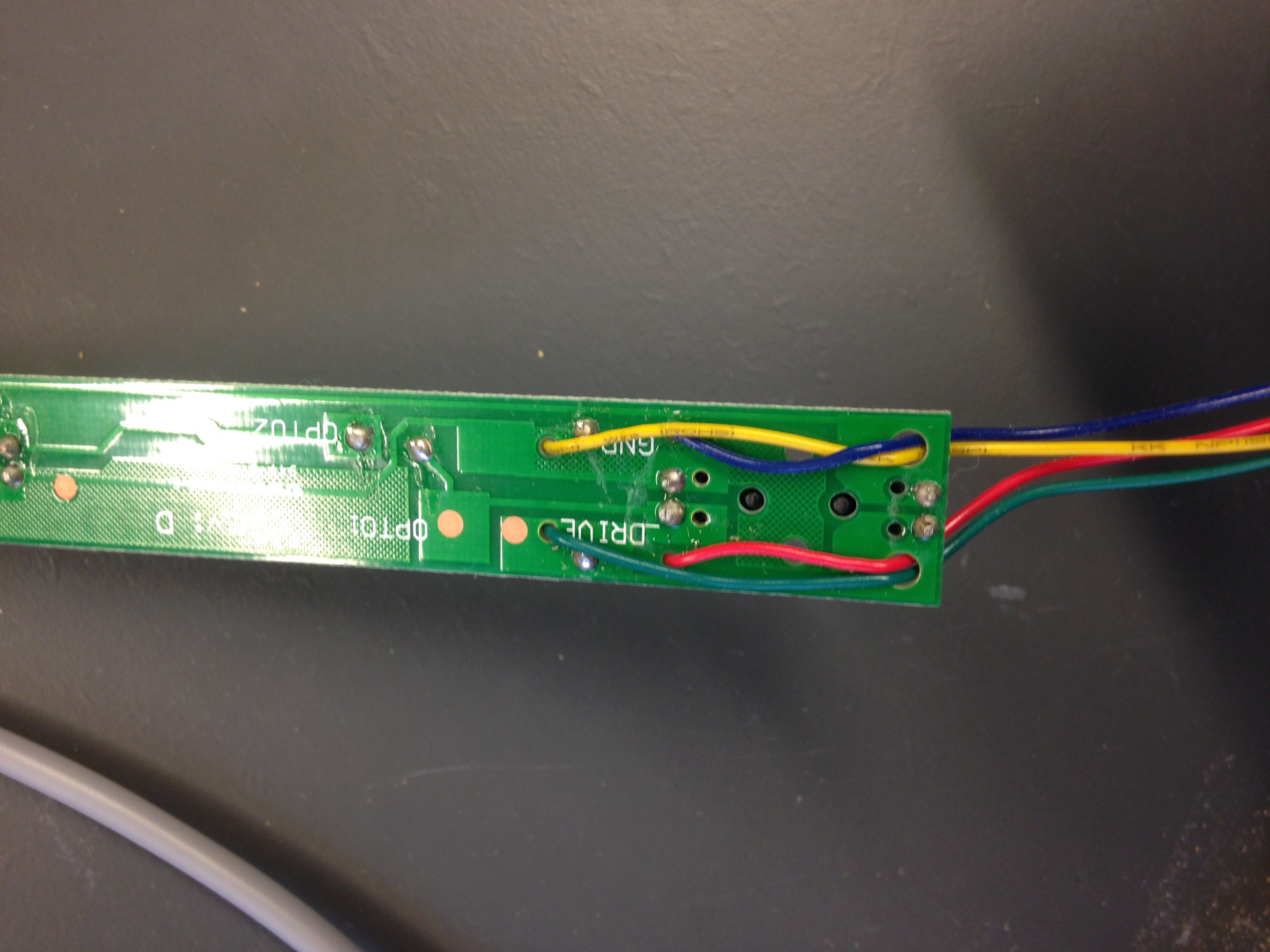
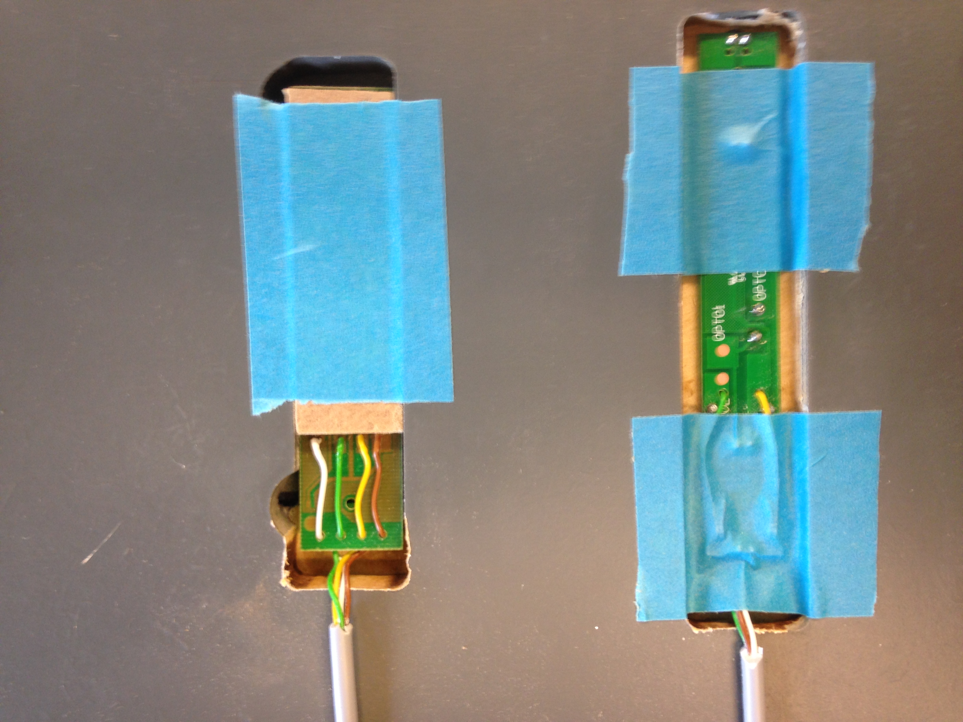
There are 3 wires from the Scalextric LC PCB to the solenoids:
WHITE = Default position (without pressing the LC button)
RED = Lane change position (pressing the LC button)
BLACK = Common
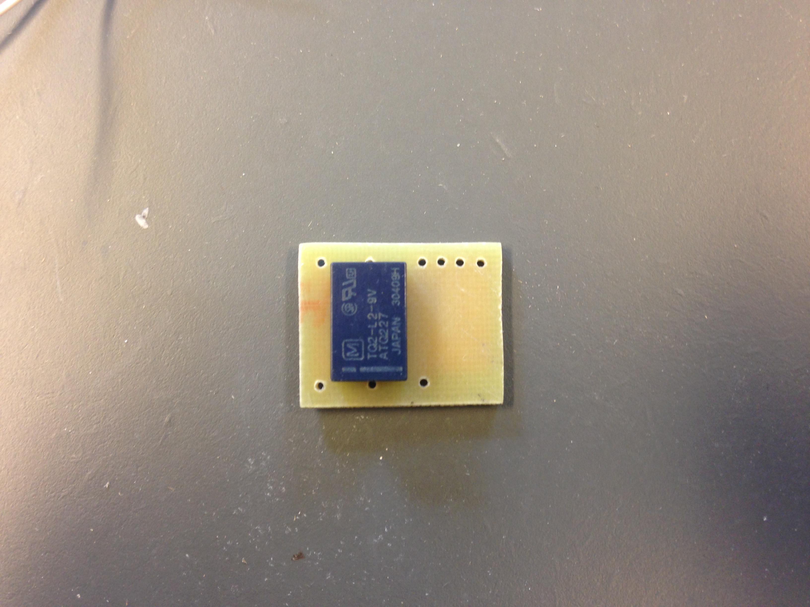
I have connected the 3 wires from the Scalextric LED PCB to the two solenoids, that output is also connected to a small relay PCB. The relay will change position with the solenoids. The contact set on the relay, is connected to track power (NC/NO) and the LC flipper (C) and thereby secure that the flipper, always have the right potential. I haven’t used any electronic protection diodes on this relay PCB, because they already are located on the Scalextric PCB, due to the two solenoids.
Anti colliction LC
Clip 2: The car just behind the leading car, is guided to outer lane with possibility for overtaking.
Clip 3: The car attacking from inner lane, force the car in outer lane away from the default racing line and thereby avoids a collision.
Passive out flipper
To be sure that the passive out flippers, at all time, has the right potential, I have connected two SOS‘, one in each lane before the flipper, to a small PCB. The contact set on the relay is connected to track power and the flipper it selves.
Clip 4: The potential of the flipper i always right.
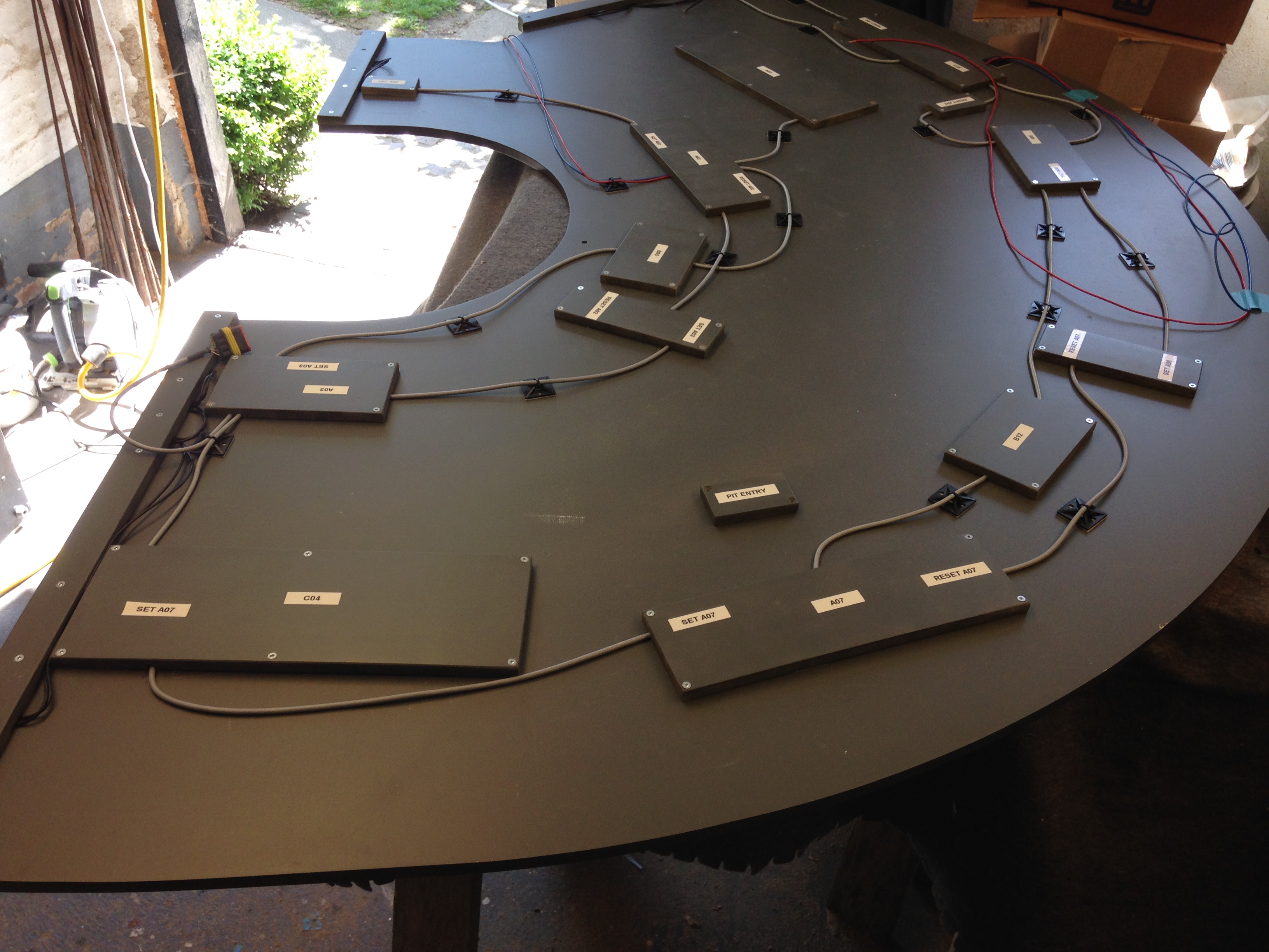
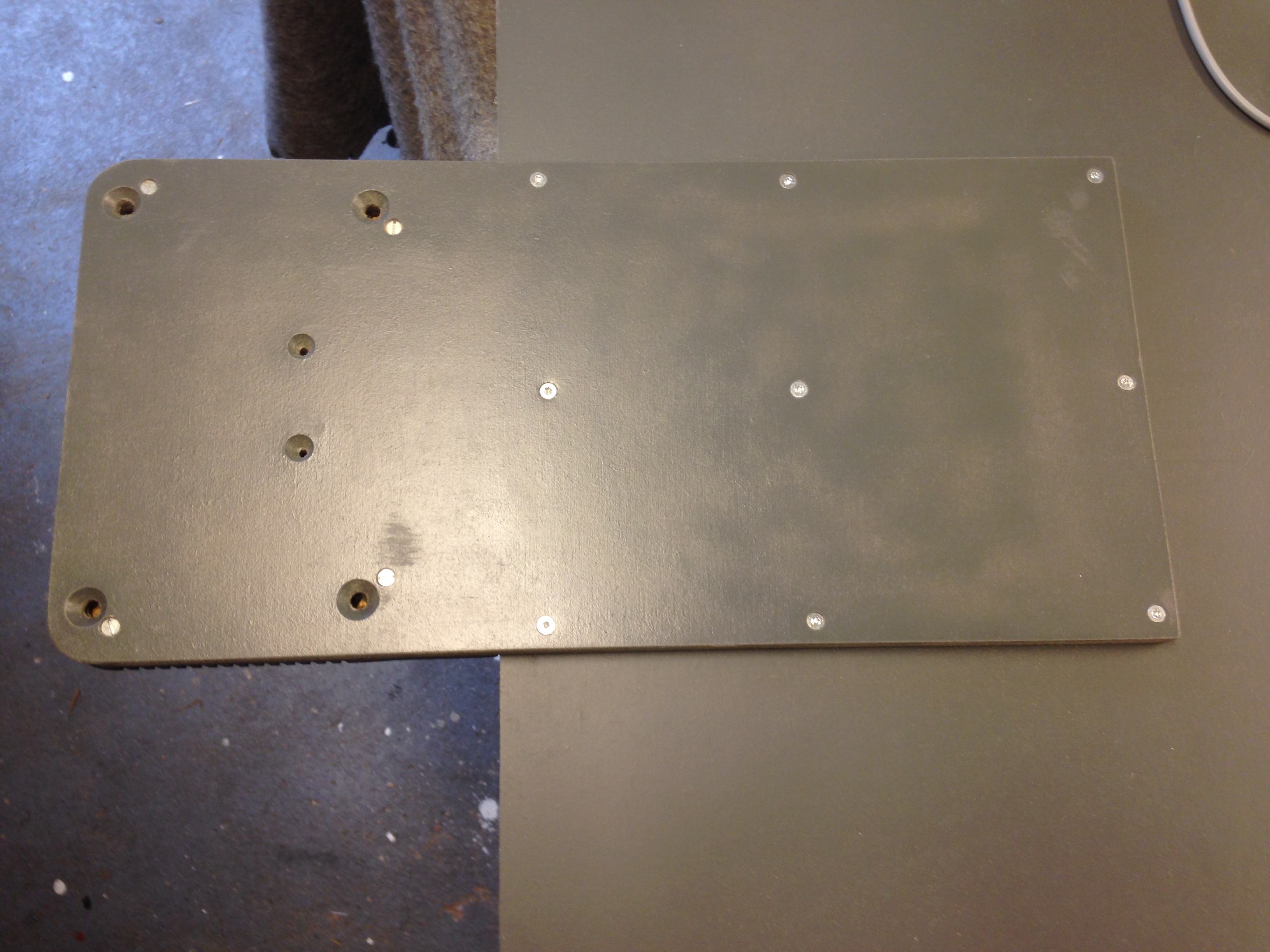
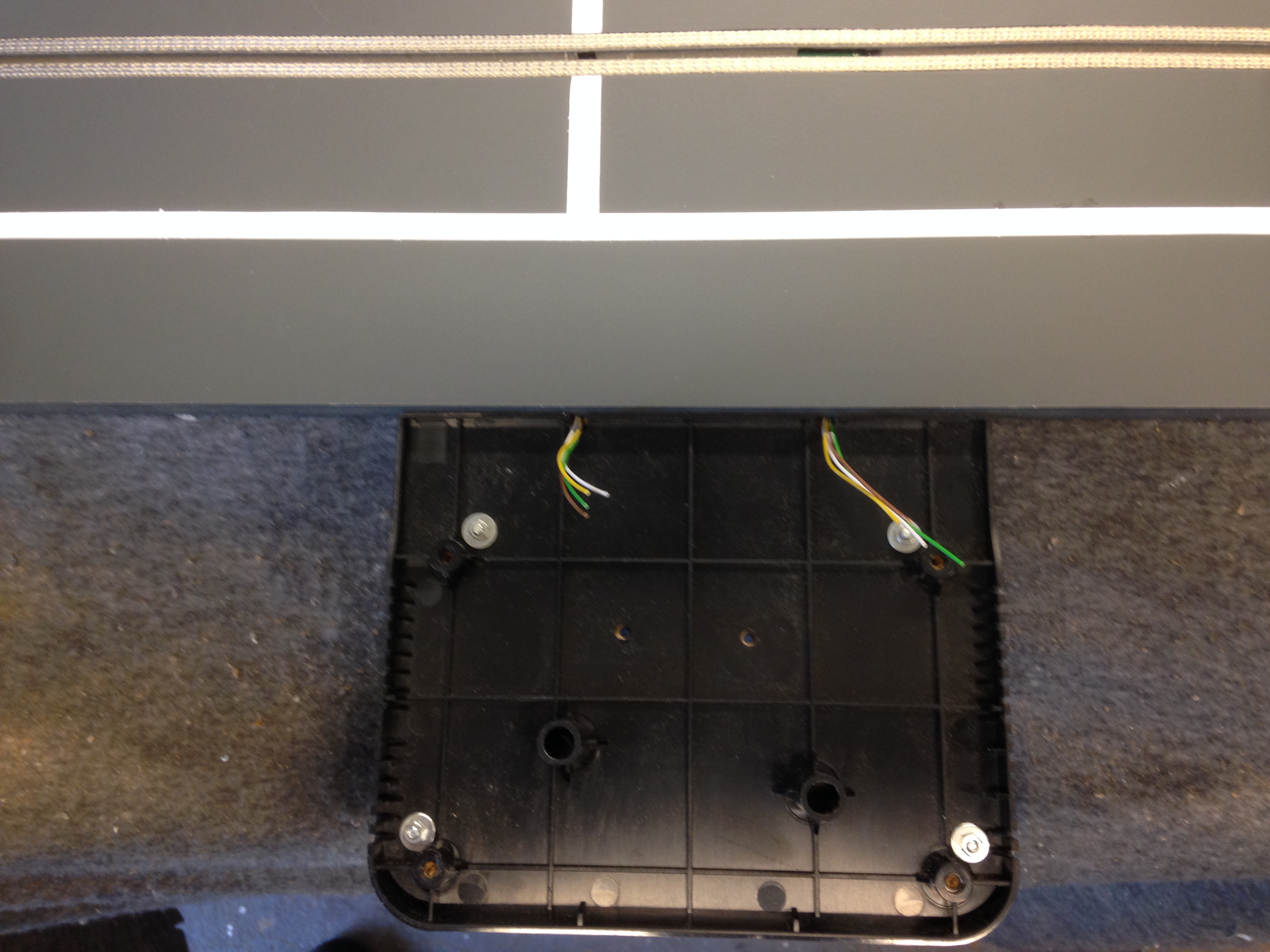
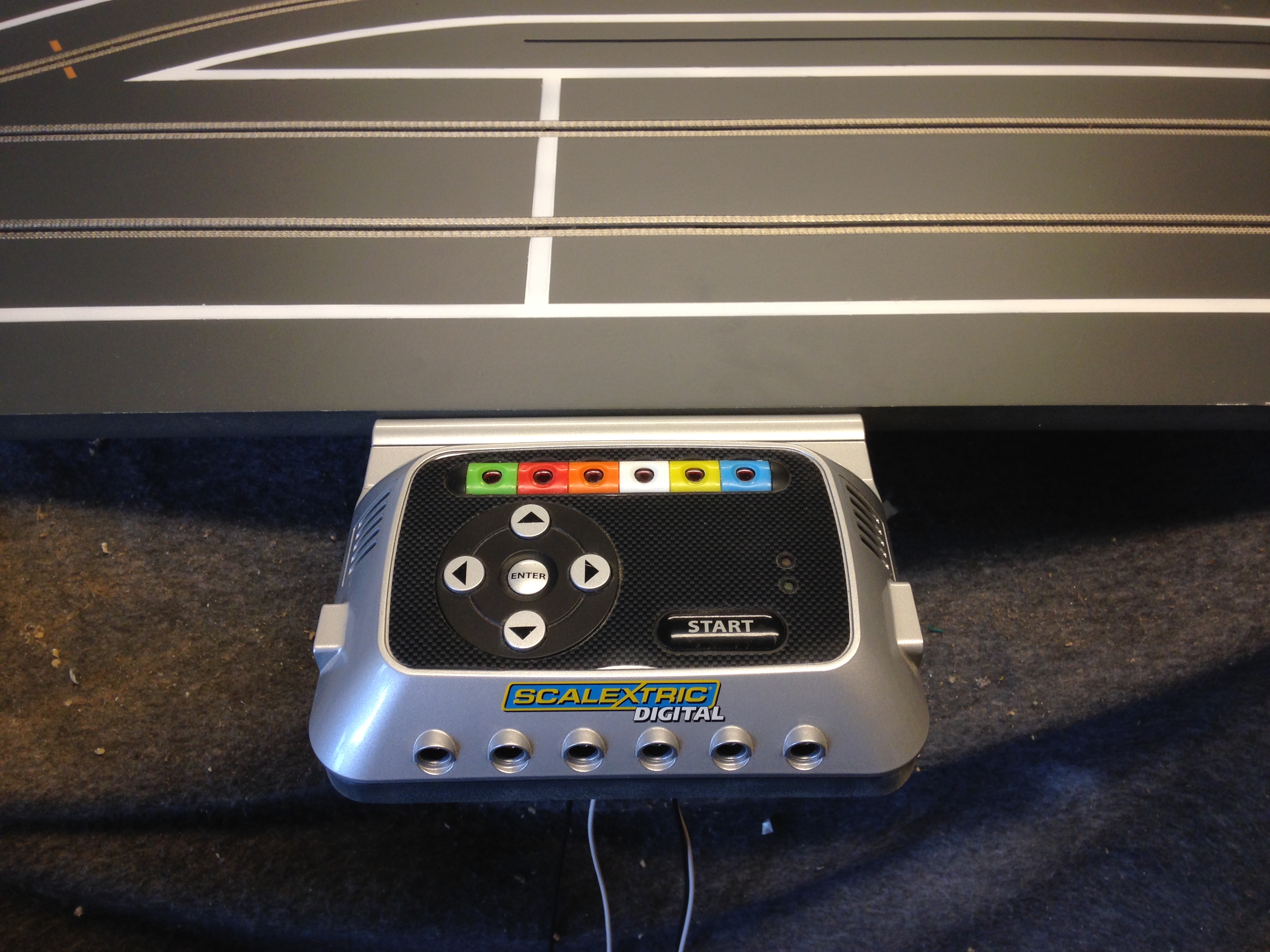
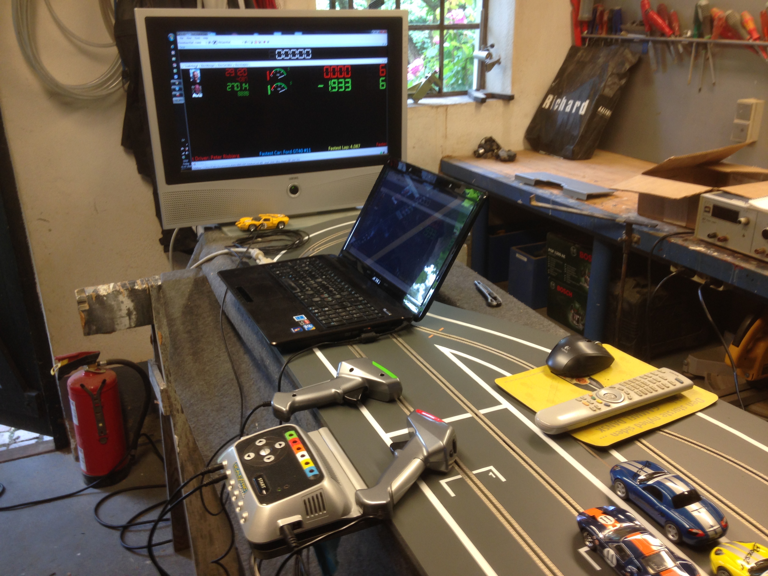
Scalextric Power Base
I had to extend the wires between the PB and the two track PCB‘s due to the width of my track. The PB is connected to my Laptop with a RikoRocket cable.
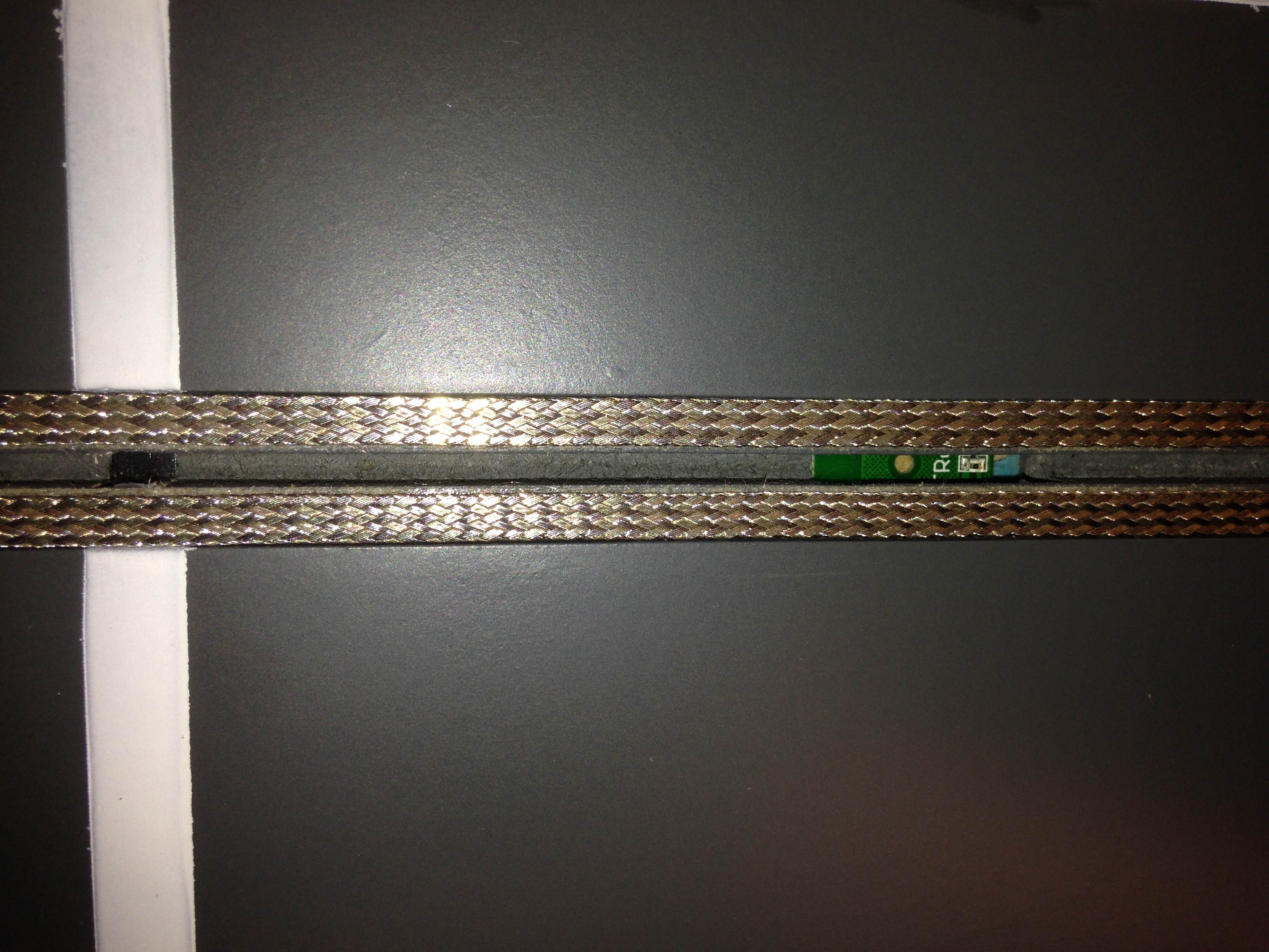
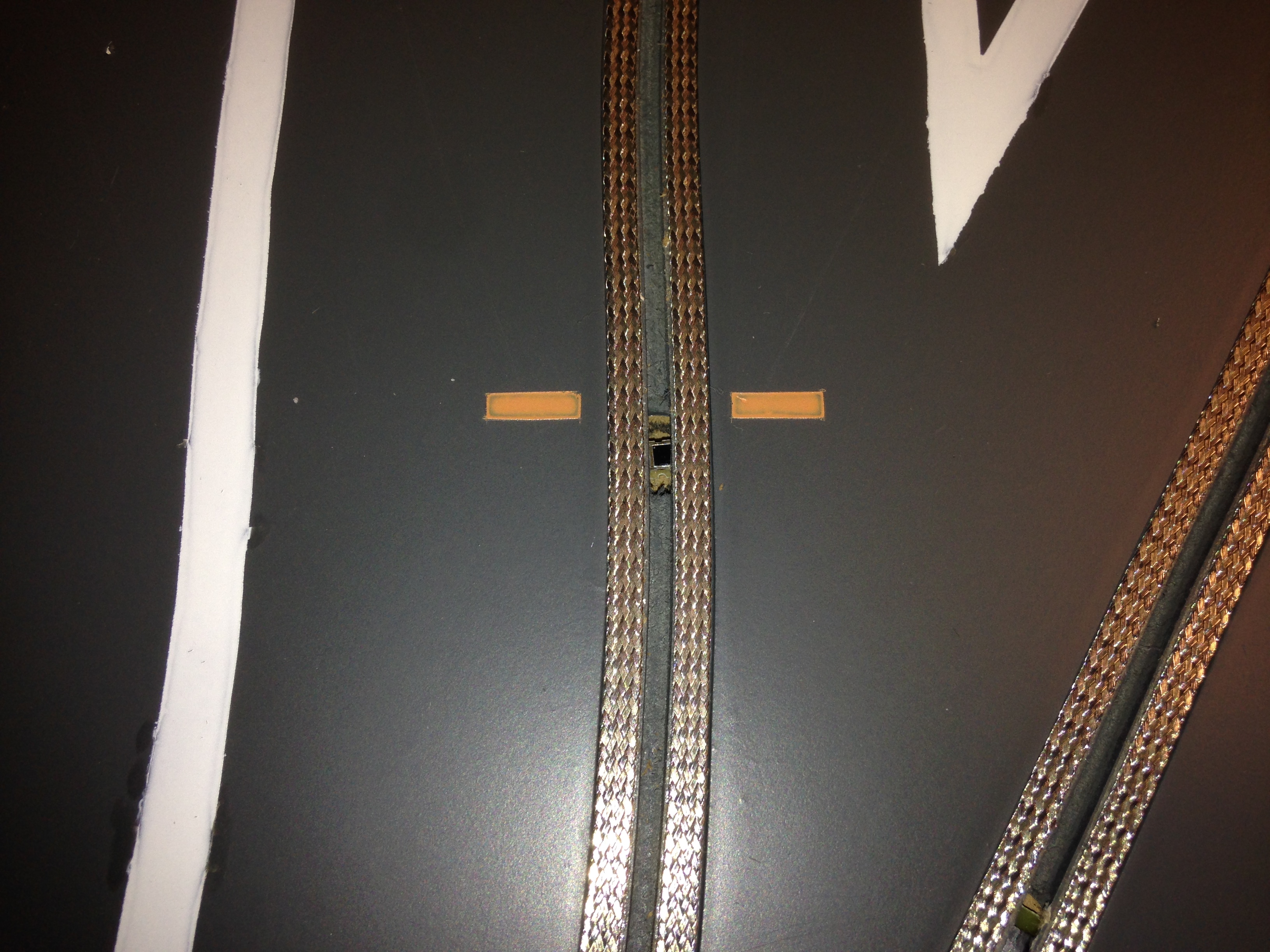
Smart Sensor
The speed will be automatically reduced when entering the pit. There is a LED at the pit entry and one at the exit connected to the PC’s USB through a Arduino Board.