
Anti collisions system
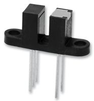
For each LC is used 4 slotted optical switches with a 3 mm gab. For changing the flipper from the racing line to the alternative line, there is one located about 300 mm before the flipper on the alternativ line and another one on the racing line just after the flipper. (Picture 1 – SET A.02) The optical switches for changing the flipper back again, is one located on the racing line just after the static out flipper and the last one on the alternative lane. (Figure 1 – RESET A.02) The last one is only mounted to secure that the flipper will be change back again, if the car on the racing line is derailed and therefor not able to reset the flipper.
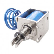
The solenoid I use has a 10 mm linear travel with spring return, its consumption is 300 mA and has a force of 4N. I have chosen to mount it 40 mm from the axle of the flipper in a middle position, so there is a bit of spring force, to hold the flipper firmly to the edge of the slot.
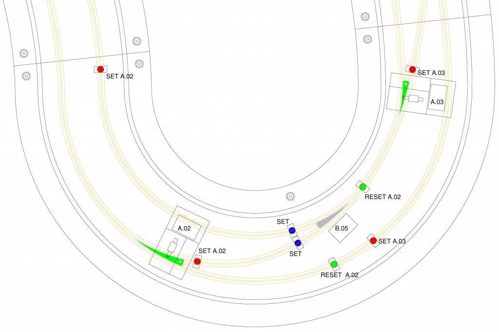
Figure 1: This is turn 2 on my track, where you can see the position of the optical switches for SET and RESET of the LC flipper.
Live IN and OUT flipper
We all know how irritating it is, to park the car on a flipper and it needs a push, to get on going. That won’t happen on my track, I want all flippers to be “alive”.
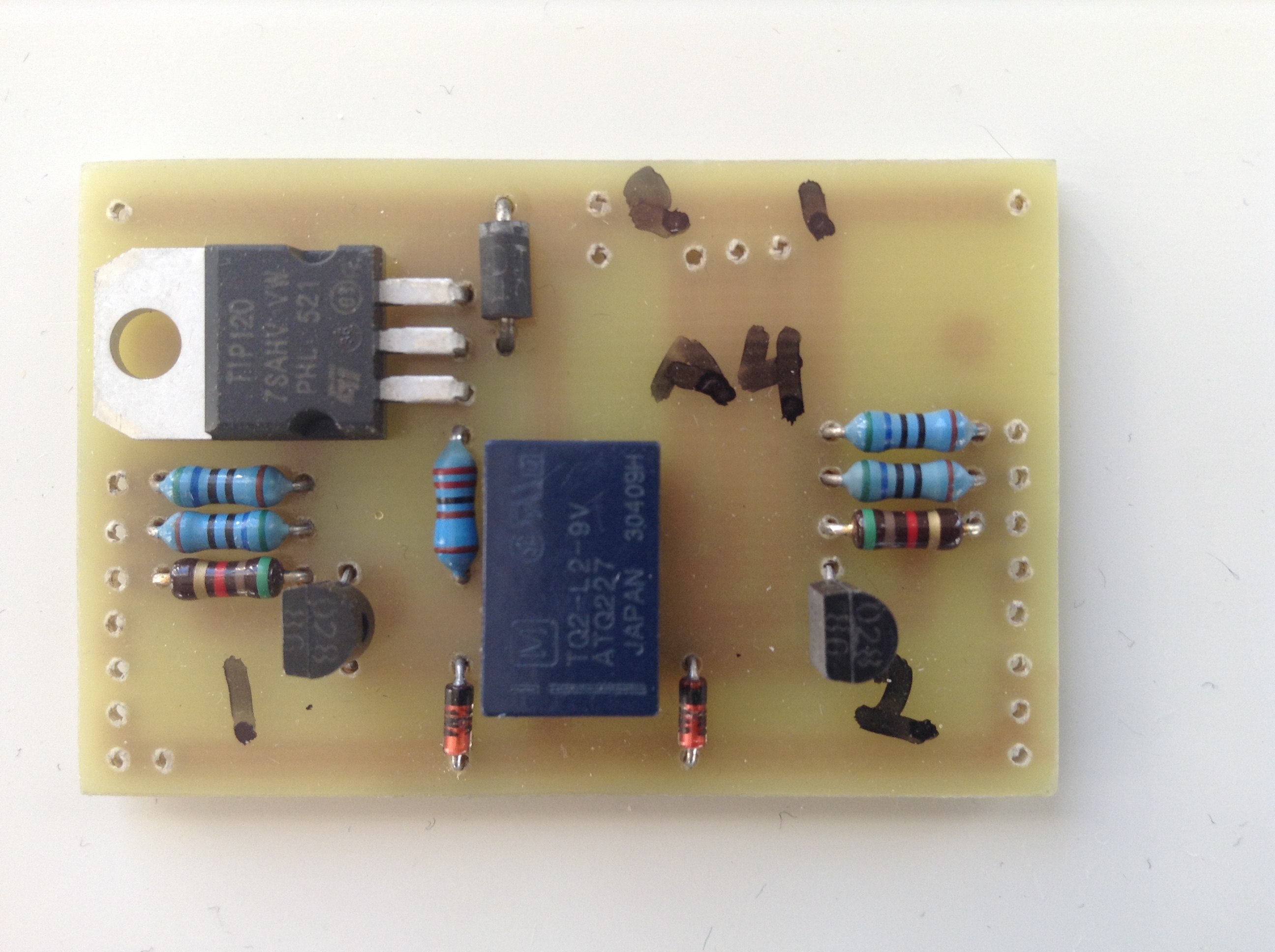
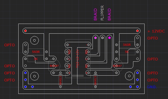
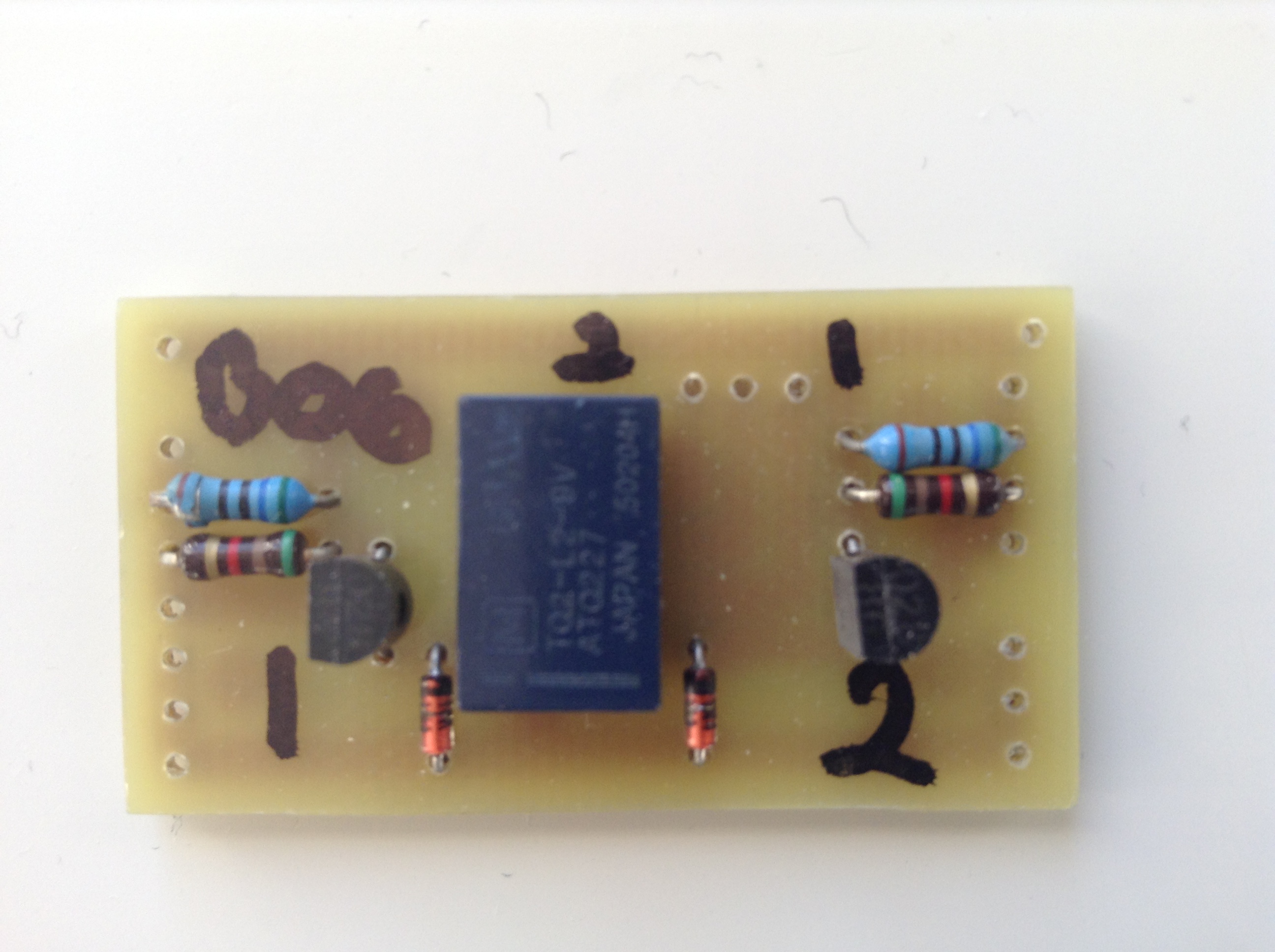
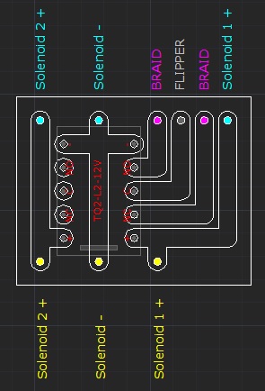
The IN flipper gets it’s potential from one of the two contact set on the LC‘s PCB relay, which controls the position of the LC flipper and therefore know what potential the flipper should have.
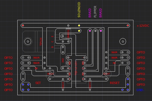
The OUT flipper need to have it’s own PCB, connected to 2 slotted optical switches to secure that the static flipper has the right potential. The optical switches are mounted just before the flipper, one in each slot (Figure 1 – B.05). The Common (C) on the PCB‘s relay is connected to the OUT flipper itself and Normal Closed (NC) and Normal Open (NO) to each braid, just like the active one.
Scalextric LC
I will use my already purchased Scalextric digital LC parts, for the pit entry, for a lane change inside the pit area and the rest located around the track. (See ‘Track Design‘)
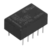
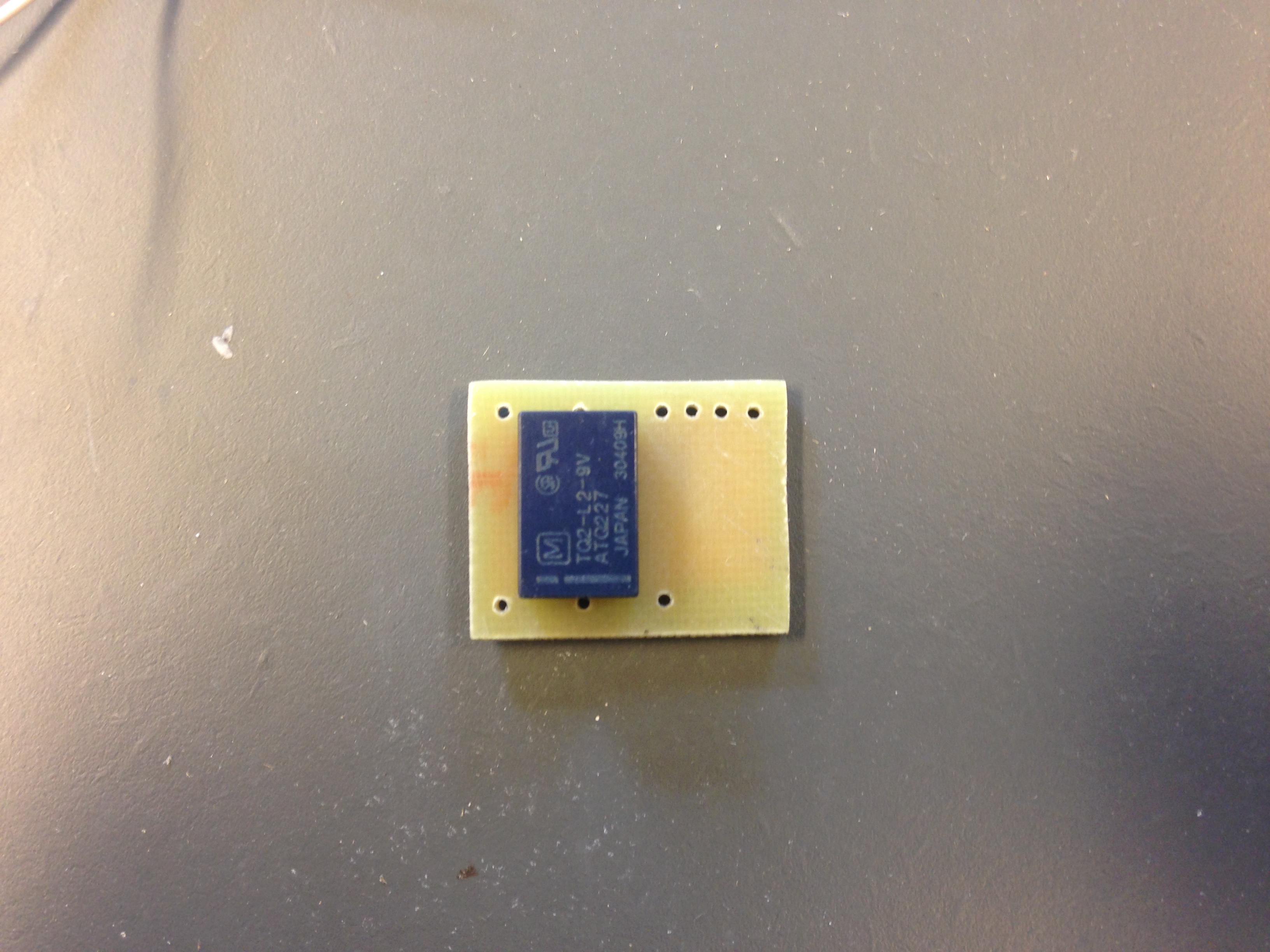
Between the Scalextric solenoid PCB and the two solenoids it selves, I have mounted a dual coil latching relay, like the ones I use on my other PCB‘s, to secure that a parsing car is provided with the right potential.
Scalextric have their LED detection point about 200 mm from the tip of the flipper and the detection hole to the LED through the rail is Ø 5,5 mm. My slot is 3 mm wide and I don’t want to make a slip in the braid where the LED is located. That’s why I have tested, how side ways a car can pass the LED and still have a reliable detection through a Ø 3 mm hole in a depth of 6 mm. The result was 15° and therefore I have located the Scalextric LC‘s, where cars don’t exceeds that limit. Should there during testing be any problems, I do have the opportunity to increase the diameter to Ø 4 mm, because my braid router is 14 mm wide and the braid is 5 mm, which gives me 0,5 mm extra space on each side. (14 – (2 x 5 + 3) = 1)
PSU
All the electronic for the anti collision system and Scalextric LC‘s, will be powered by a separate 12VDC PSU and will therefore not affect the voltage output from the 2 Scalextric PSU‘s connected to the PB.